- Hardware Manuals
- Commissioning and Tuning Guide
- Software Reference
- Resources
In this document
SOMANET Braking Chopper 48V 500W is a braking chopper (also referred to as shunt or regen board) that can be used in conjunction with other SOMANET products, in particular SOMANET drives. It is used for consuming excessive energy that may appear on the DC bus while a motor decelerates a load. The Braking Chopper 48V 500W is capable of dissipating 430 W peak power and up to 90 W continuous power if adequate cooling is provided.
When the motor is used for actively decelerating a load, electrical power will be regenerated. If the drives are supplied by a standard power supply (with no recuperation function), such regenerative operating points will cause overvoltage on the DC circuit, thus either the drive or the power supply will shut down.
To prevent this from happening, a shunt circuit is needed to burn this recuperated energy.
More information about regenerative energy and how to use Braking Choppers can be found in our System integration guide.
General Specifications |
|
|---|---|
Standard Bus Voltage |
48 V |
Activation threshold voltage V_th* |
Adjustable by the user to be 50, 53, 54, 55 or 57 V |
Maximum voltage increase on the DC bus ** |
V_th + 5 V |
Absolute Maximum Voltage |
Up to 63 V |
Rated continuous power |
30 - 90 W, depending on cooling situation and duty cycle |
Peak Power |
430 W |
Period to apply peak power |
250 ms |
Ambient temperature for power ratings |
Room temperature (20 °C) |
Maximum system temperature |
< 95 °C |
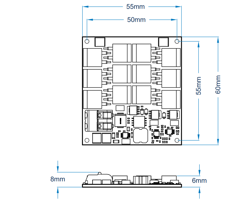
Dimensions |
55 x 60 x 8 mm |
Weight |
42 g |
*This voltage defines the voltage at which the first shunt starts getting active
**The voltage on the DC bus may increase up to 5 Volts above the threshold voltage (as long as the regenerated power is below 430 W) for a short period of time. Please consider this when designing your system
The Braking Chopper can dissipate up to 430 W for periods of 250 ms. In pulsed operation (as it typically appears in robotic applications), the average power to be dissipated can be up to 90 W. Please ensure that the Chopper Board is mounted on a proper surface that has a large enough volume for dissipating the generated heat.
The shunts of the board will be activated if the voltage is above the Threshold Voltage with a deviation of 1%.
To install your module, mount it in an appropriate place with good cooling. Make sure the bottom is connected to some metal structure thermally conductive.
Important
To ensure optimal performance, an appropriate heat conductivity is essential. It is recommended to use silicon paste or a thermal pad.
Attention
Because the mounting holes are connected to the GND plane in the PCB, the isolation will break when a conductive Spacer is used between the mounting holes on the PCB and chassis. This can violate an existing earthing system and if a SELV power supply is used it may become PELV.
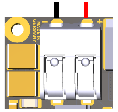
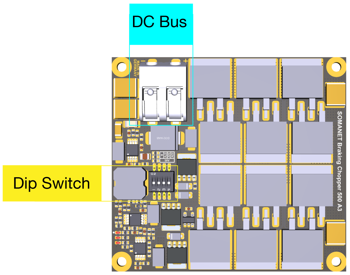
Connect the braking chopper wires to the DC bus. The chopper board must be installed in parallel to drive boards. To set the threshold voltage please use the dip switches found on the top side of the board in five levels: 50 V, 53 V, 54 V, 55 V or 57 V.
Note
Please ensure that the nominal voltage of the DC bus is lower than the configured threshold voltage. Otherwise, the Chopper Board will be permanently ON. This is important for battery driven applications if the full charge battery has a higher voltage.
SW1 |
SW2 |
SW3 |
SW4 |
Threshold Voltage |
|---|---|---|---|---|
Reserved |
OFF |
OFF |
OFF |
50 V |
OFF |
OFF |
ON |
53 V |
|
OFF |
ON |
OFF |
54 V |
|
OFF |
ON |
ON |
55 V |
|
ON |
X* |
X* |
57 V |
* Either OFF or ON
1857 BK005 (black) and 1857 RD005 (red) from Alpha Wire: Stranded, 18 AWG, 7/26
781801 BK005 (black) and 781801 RD005 (red) from Alpha Wire: Solid, 18 AWG
For a permanent cable solution (16-22 AWG), this Pin Connector is recommended: 165167 from TE
In case the power on the DC bus exceeds Peak Power or shunts reach their temperature limit, the shunt will be deactivated in order to prevent the resistors from burning. In that case, the DC bus will behave just like it would without any shunt installed. Thus, the DC bus voltage will keep growing until the Drive’s overvoltage protection triggers.
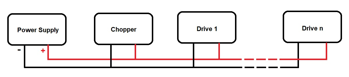
Several SOMANET Chopper 500 boards can be used on the same DC link, by just connecting them in parallel. This way, their peak power and average power will add up.
The required overall shunt power in a robotic system depends on many factors, including the robot’s inertia, payload, number of axes, size and type of motors, trajectory, controller settings, braking and quick stop strategies etc. There is no universal rule of thumb indicating how many SOMANET Chopper 500 boards are required for a certain number of motors. Developers should compute the regenerative powers and energies in their robot’s respective load cycle or measure these values in experiments.
Some practical guidelines to begin with:
If decelerations and loads are moderate, one Chopper 500 can cover the regenerated energy of several Drives. In many real-world applications, this is already enough, so one Chopper 500 per robot is often sufficient.
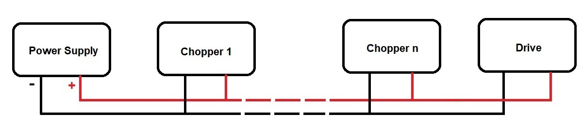
A setup combining one Chopper 500 with one drive allows for very demanding applications. However for test bench experiments or extreme trajectories including very sharp braking beginning abruptly at maximum speed, one Drive 1000 can even exceed the capabilities of one Chopper 500.
The number of necessary chopper boards is a question of the multi-axis system setup, not a question of every particular drive.
For an optimal overall system setup, up to 12 chopper boards can be connected in parallel to the same DC bus. Their power dissipation capacity will add up.
You can start first test runs with slow trajectories and one chopper board and monitor power that goes to the chopper board during operation. Decreasing the cycle time will increase this power. In case that either peak or average power approach the allowable limits, the cycle time should not be reduced further before adding another chopper module.
In case the chopper system is undersized for the requested load cycle, the SOMANET Chopper 500 either deactivates itself due to thermal protection or it is just not able to drain the amount of current that it would need to drain in order to keep the DC bus voltage constant. In either of these two cases, the DC bus voltage will increase until the SOMANET Drives shut down themselves due to overvoltage.
Attention
An undersized chopper system can lead to dangerous situations when the robot isn’t able to decelerate as necessary.
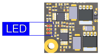
The board is equipped with three LED indicating the amount of energy being burnt on the Braking Chopper. The board has three stages and each LED represents one of these stages.
Note
When all LEDs are turned on, it means that another Chopper might be needed. However the DC bus voltage is still needs to be measured to determine how many choppers are necessary.