- Hardware Manuals
- Commissioning and Tuning Guide
- Software Reference
- Resources
The general purpose of the position control loop auto-tuning is to design position controller gains based on user specifications and the identified model of the set-up. The procedure calculates gains for the cascaded controller configurations: PI-P, P-PI.
Before conducting position auto-tuning check the following:
The System Identification has been executed successfully.
The obtained model corresponds to the current configuration of the system. Otherwise the identification procedure should be repeated.
If different sensors are used for position and velocity control and there is a gearbox in between, the gear ratio should be specified.
Make sure that the sensors are mounted properly and calibrated.
The procedure uses a linear mathematical model of the system. If there are strong nonlinearities there will be a difference between the actual and the requested performance.
The auto-tuning procedures tunes only linear controllers. Non-linear control parts should be tuned manually for better performance.
Hall sensors should not be used for precise position control.
Select “Controller Configuration” from the menu. Currently, two options are available that have different behavior:
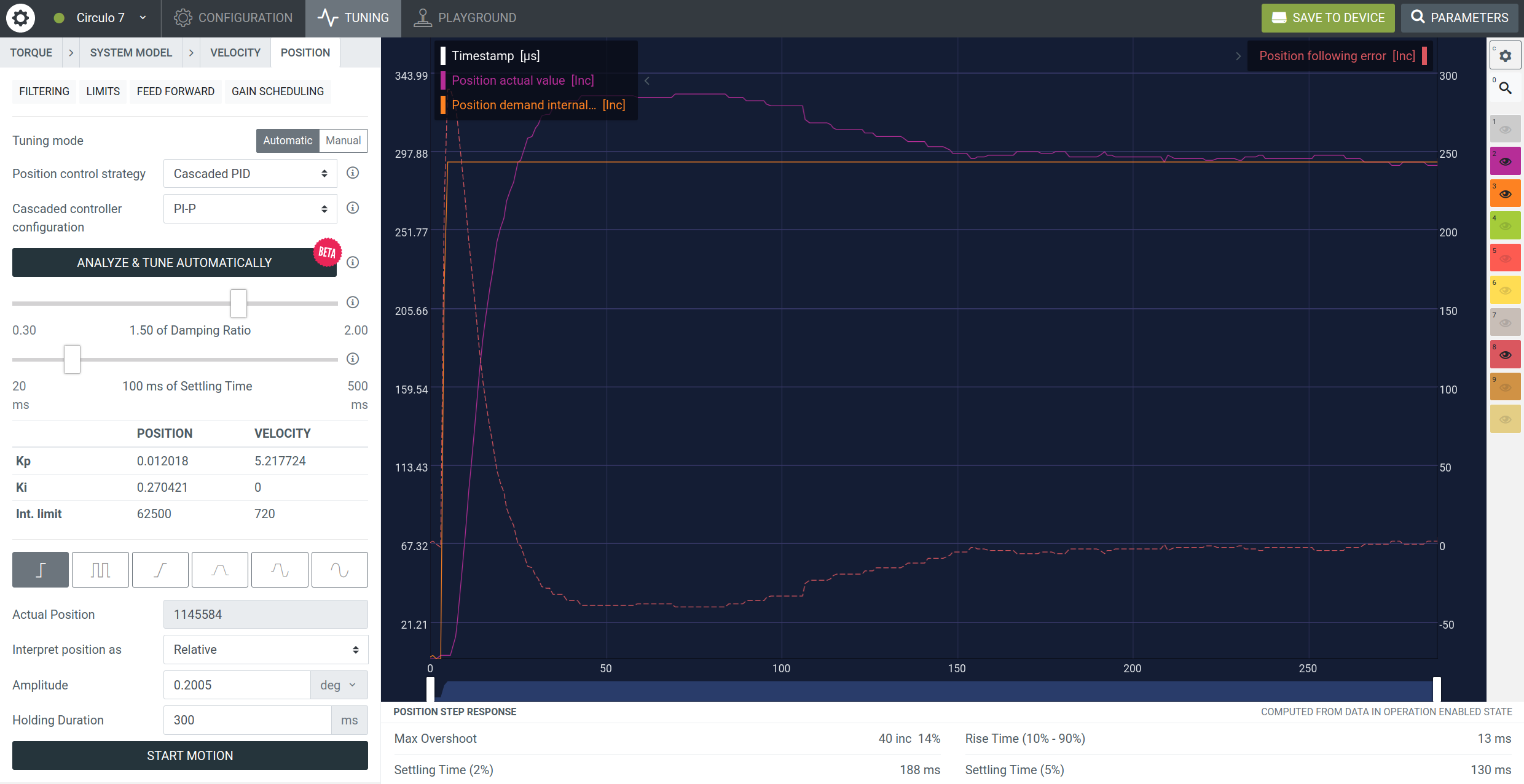
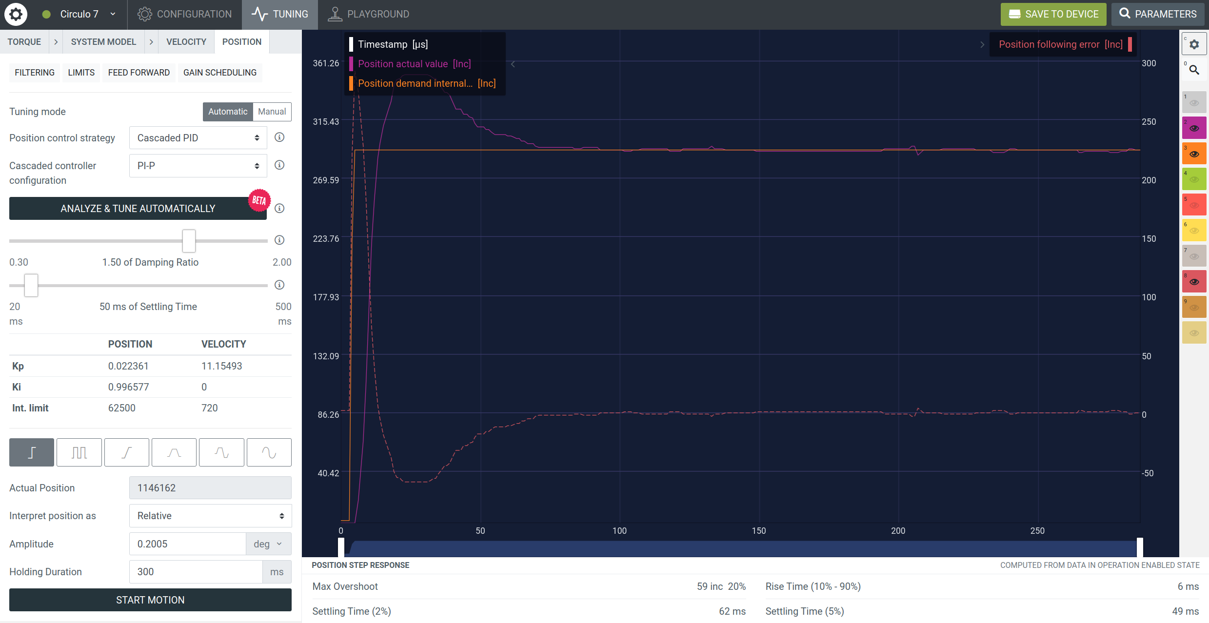
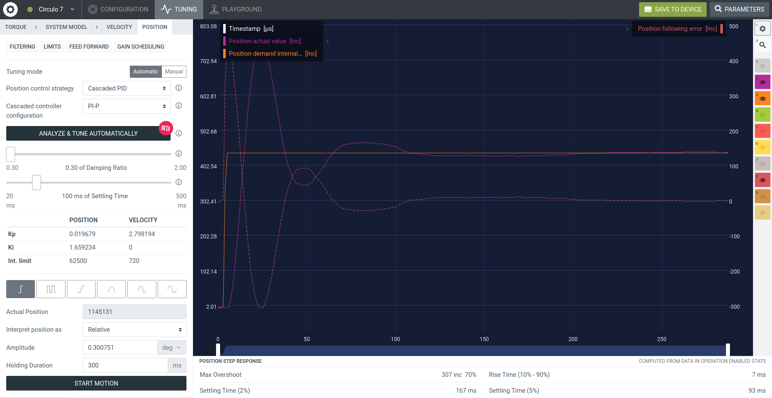
PI-P configuration (default) focuses on trajectory following. Generally it has a faster response, zero steady state error for constant and ramp reference inputs. The control loop bandwidth is higher than the P-PI configuration. However, it tends to overshoot:

P-PI configuration focuses on soft damped step response. It has a slower response and less precise tracking, however it is usually possible to fully avoid overshoot. Additionally, it is more sensitive to noise in the velocity signal:

The controller gains are updated automatically every time the sliders are dragged and released. The gains calculation has an optimization loop inside and may take a few seconds.
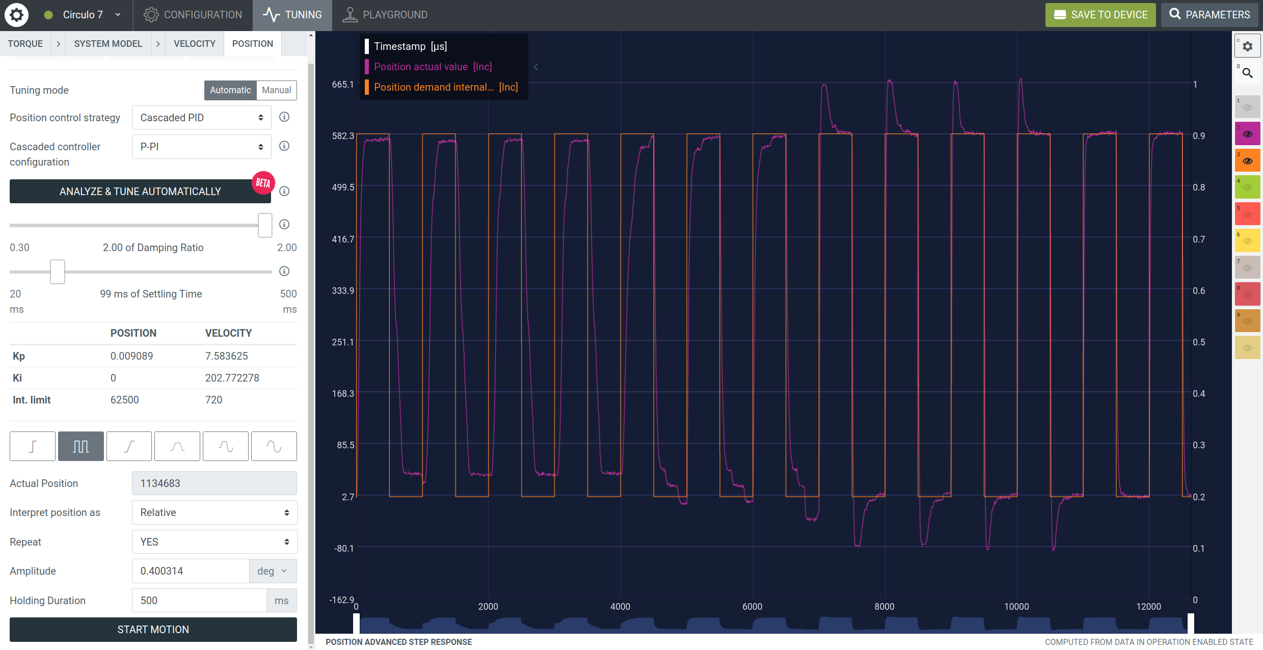
After the initial tuning is done, it is possible to tune the control loop more precisely by changing the gains while executing a test signal. There are currently 4 repeatable test signals: square wave, ramp, bidirectional ramp and sine. It is possible to drag sliders and manually change gains during the reference signal following:
There are 2 sliders that allow users to specify the demanded performance of the control loop:
Settling time is the time [in ms] needed to settle the step response within 2% of the reference value. The auto-tuning procedure will try to find gains to ensure the specified settling time given the identified model.
- Settling time of 100 ms:
- Settling time of 50 ms:
Damping ratio is a parameter that reduces oscillations in an oscillating system. In a cascaded control loop, this parameter indirectly influences overshoot and rise time. Practically, the damping ratio effect depends on the controller type.
Values > 1 can be used for removing overshoot but at cost of slower settling time, it may also lead to undershoot and non-zero steady state error.
- Damping ratio is maximal:

Values < 1 can be used to achieve a sharper response and a better bandwidth at a cost of overshoot:
- Damping ratio is minimal:
After tuning your motion control system, you can for example improve performance by using these features:
Removes ripples caused by magnetic interaction between motor rotor and stator.
Digital filters can be used to remove unwanted frequencies such as noise or nonlinear effects.
Applies controller gains which will change dynamically regarding the current speed.
# Do I need to manually adjust controller gains after the auto-tuning?
Usually, sliders provide enough flexibility to achieve demanded performance. Mismatches between requested and actual step response can be compensated by entering a faster settling time.
# Can I define other position/velocity/torque units in the custom firmware?
The auto-tuning will provide gains only for default units.
# What if my encoder has low resolution?
This will definitely result in worse performance compared to higher resolution encoders. Additionally, the velocity signal used in system identification might have multiple zeros that may result in incorrect model.
# Do I have to repeat system identification and tuning after I attached a load to the system?
It is better to repeat both procedures. If it is not possible to repeat the system identification, auto-tuning still can be used. But the resulting settling time will differ from the requested.
# What if the system is unstable after auto-tuning?
Try to input a slower settling time.
Check the motor and sensor configuration parameters.
Check the velocity signal in the playground in the torque control mode. Ensure that it shows correct data during manual rotation of the shaft.
Soften filters in position/velocity control loops. They might introduce delay.
# What if the test signals trigger overcurrent/undervoltage?
Reduce the test signal amplitude or frequency.
Increase the settling time.
Check the configuration of the motor and sensor.
Make sure that correct power supply is used.
# Is there a PID controller auto-tuning?
A simple PID is usually not used for position control.
# How do filters influence the auto-tuning?
Using a velocity filter results in a phase delay based on the filter order and its cutoff frequency. It is recommended to perform a system identification and tuning after filters were configured. Be careful, filters severely reduce stability due to phase delay.