- Hardware Manuals
- Commissioning and Tuning Guide
- Software Reference
- Resources
In some cases, the motor is equipped with a mechanical brake which can be released by applying electrical voltage to the brake’s terminals.
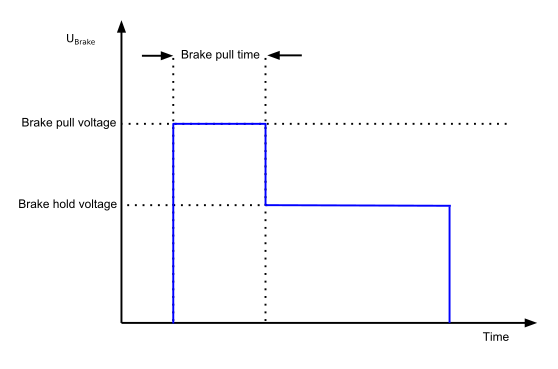
A configurable voltage is applied to the positive terminal of motor brake (It is assumed that the negative terminal of the brake is connected to Ground).
When the motion system has entered operation enabled, the specified “Brake pull voltage” will be automatically applied for a configurable amount of time designated as “Brake pull time”. After this time period, the second voltage level “Brake hold voltage” will be applied to the brake terminals permanently. The brake hold voltage can be set to a lower value to save energy.
Attention
Don’t set the hold voltage too low or you risk entering a marginally stable situation where any jerk can engage the brake.
Once the motion system leaves the state “operation enabled” the voltage is automatically dropped to Ground after the designated time “Brake engage delay” and the brake is mechanically activated.
A pin-brake is a special type of brake commonly used in light-weight robot joints. The brake usually consists of a solenoid linear actuator fixed to robot body and a notched wheel fixed to the rotating motor shaft.
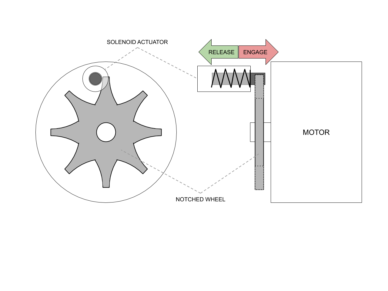
To release a pin-type brake, the motor must move slightly so that the pin can slide out. This is mainly required with hanging loads (e.g. robot arm) where gravity is producing a torque pressing the wheel notch against the actuator pin. The following method is implemented to ensure reliable pin-type brake operation.
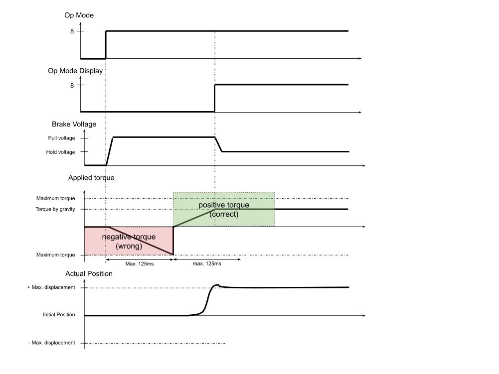
The brake controller raises the torque progressively until it reaches the maximum displacement threshold. If it reaches the maximum torque threshold first, it rises the torque again in the opposite direction. When the torque is high enough to compensate for gravity, the load is lifted until the position reaches the threshold value, the torque stays to a holding torque value and the brake will be disengaged. After the release delay, the brake voltage is driven to “Brake hold voltage” and Op Mode display is set to Op Mode. The controller is then enabled. To use the pin-brake mode please select the correct “Release strategy” in the brake configuration section in OBLAC Drives commissioning software, or via direct object dictionary access.
Note
The brake release is an open loop system. After the brake pull time it is assumed that releasing was successful and the hold voltage is applied.
The PWM frequency of the brake can be changed in object 0x2004:11 Brake options: Switching frequency.
Enter the value 0 for 16 kHz
Enter the value 1 for 32 kHz
Enter the value 2 for 64 kHz
It is also possible to implement custom brake modes. For information please refer to Manually controlling phase D voltage
