- Hardware Manuals
- Commissioning and Tuning Guide
- Software Reference
- Resources
Attention
The magnetic encoder rings are densely packed with magnetic information. Any contact or even close proximity with external magnetic fields may destroy them permanently! Please consult our handling instructions for details
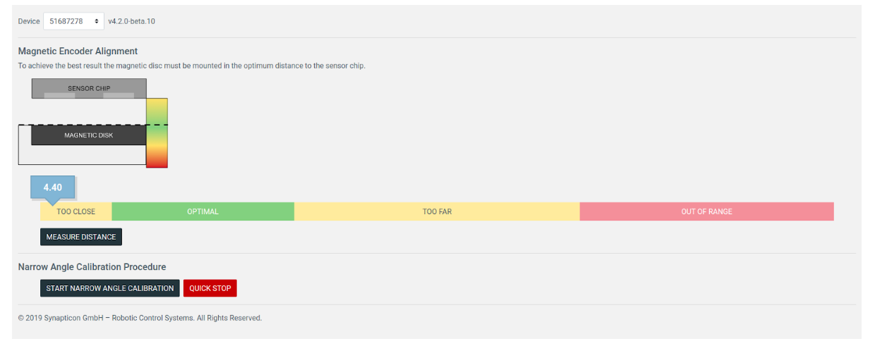
The correct alignment of the magnetic rings and the encoder module is very important for achieving a maximum of encoder accuracy and motion control performance.
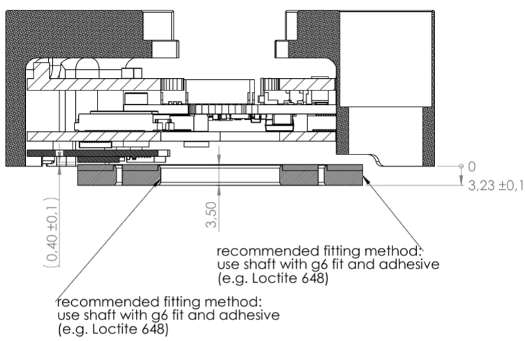
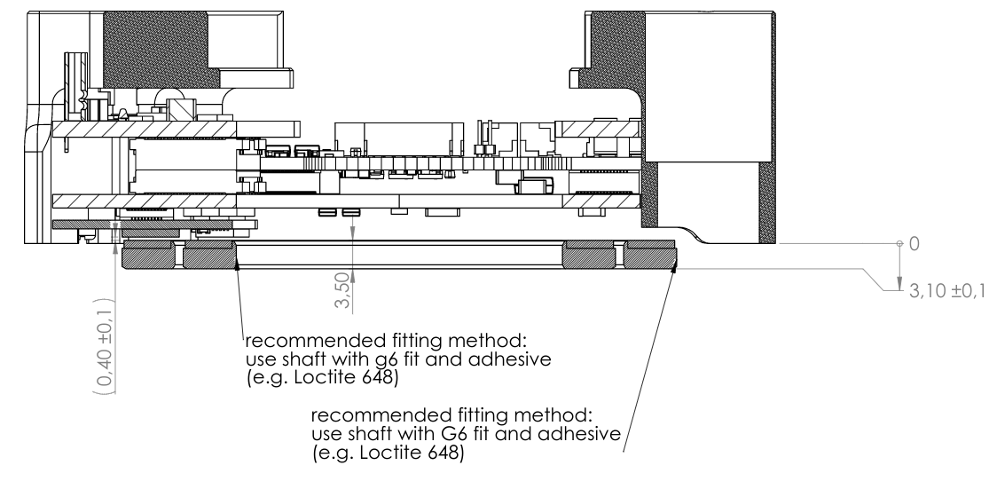
For optimal performance please mount the encoder at a distance of 0.4 mm +/-0.1
Mounting the chip closer than 0.3 mm will result in noise distortion that can not be removed by analogue calibration or by a filter.
Mounting the chip further than 0.5 mm will result in a distortion once a revolution and a superimposed distortion that grows with increasing distance. However, they can be successfully mitigated by analogue calibration. This allows to mount the chip even 1 mm from the magnet with satisfactory performance.
Note
If your application has limited requirements in accuracy, you can use these fallback values: 0.5 mm +/-0.25
This is not recommended for productive use.
Assembling the encoder system in compliance with the following tolerances will allow to reach the specified accuracy after the calibration procedures.
Parameter |
|
|---|---|
Radial displacement r |
max 0.5 mm |
Tangential displacement t |
max 0.5 mm |
Axial distance (from disc to encoder chip) z |
min 0.2 mm, optimal 0.4 mm, max 1 mm |
Mounting eccentricity (rotation axis offset) e |
max 0.1 mm |
This basically means sliding the encoder chip off the scanning track. Deviations within the permissible range increase the narrow angle error amplitude. This can be compensated by calibration. Moving the chip closer to the center of the ring will have the the most effect due to a direct influence on the main positioning (Master) track. The other direction will mostly reduce the absolute position accuracy. If increased more than specified values, the chip might fail sensing the magnetic field and throw an error.
This displacement is along the direction of disc rotation. It is typically less crucial than the radial displacement because the measured field doesn’t change as much along this axis. It reduces the absolute position accuracy.
Mounting the chip closer than 0.2 mm will result in a strong noise distortion that can not be removed neither by analogue calibration nor by filtering.
Mounting the chip further away will result in a growing angular error which can be compensated by the encoder calibration. This allows to mount the chip even 1 mm from the magnet, although the resulting performance will not be optimal.
It is possible to obtain a positioning feedback directly from the encoder chip in OBLAC Drives. This will help to adjust the axial distance.
Tilting Circulo around the rotation axis of the motor and gearbox does not create any additional error (other than affecting the zero position offset).
This is the most crucial error source and hence should be as minimal as possible. The best way to cope with it is to perform a calibration with a high accuracy reference encoder. The built-in auto-calibration procedure usually can’t fully remove this error. If this error is not removed by calibration, a periodic once-a-revolution distortion will be present in velocity and position data. This is usually known as the wide angle error or the long wave error.