- Hardware Manuals
- Commissioning and Tuning Guide
- Software Reference
- Resources
An open-loop system identification extracts a mathematical model of an electromechanical system from a frequency response. The obtained model is then used during the auto-tuning procedure.
Before conducting system identification make sure that:
The motor is connected and functional.
The system is firmly fixed.
The motor shaft can rotate.
The torque control loop is functional and the commutation offset is found.
Position and velocity signals are present and output sensible data.
Applying constant positive torque results in positive velocity and vice versa.
Note
Using a Chopper Board is strongly recommended to prevent hardware damage
The procedure should be used carefully if the system has strict mechanical limitations. Torque amplitude should be decreased until safe identification is possible.
If the system is highly non-linear, the identified model might differ from the reality.
If motion and vibration are too high, the algorithm can’t be used.
The accurate frequency response of the system can be obtained only for frequencies up to 100 Hz due to communication limitations.
If the system has very high static friction, small amplitude torque signal will overestimate viscous friction and inertia.
Note
To reset to default values simply click on the Velocity or Position tab.
For general applications the default settings can be used. Press “Run system-identification”.
Note that the amplitude of the torque test signal changes linearly from 50% to 100% of the displayed value.
Make sure that the system moves during the experiment. Velocity and torque signals on the screen are nonzero. If the system did not move, the torque amplitude should be increased. A higher motion amplitude is recommended to ensure the system is in the viscous friction region.
Wait until the procedure is finished.
Increasing the identification signal frequency range will result in detecting resonances of the system. However, inertia estimation will be less precise due to overfitting.
There are 2 sliders that allow users to change the frequency response test signal:
Adjust the slider from smaller to bigger values so the system moves in a safe range and vibrations are still acceptable. The resulting velocity should be nonzero and have the same sign as the torque at the beginning of the experiment.
Low values result in smaller vibration amplitude, less stress on the mechanical structure but low signal to noise ratio may result in an imprecise model. Additionally, if static friction is present and the system moves slowly, the algorithm will overestimate the load inertia and the friction constant. An example of low amplitude can be seen in the image below:
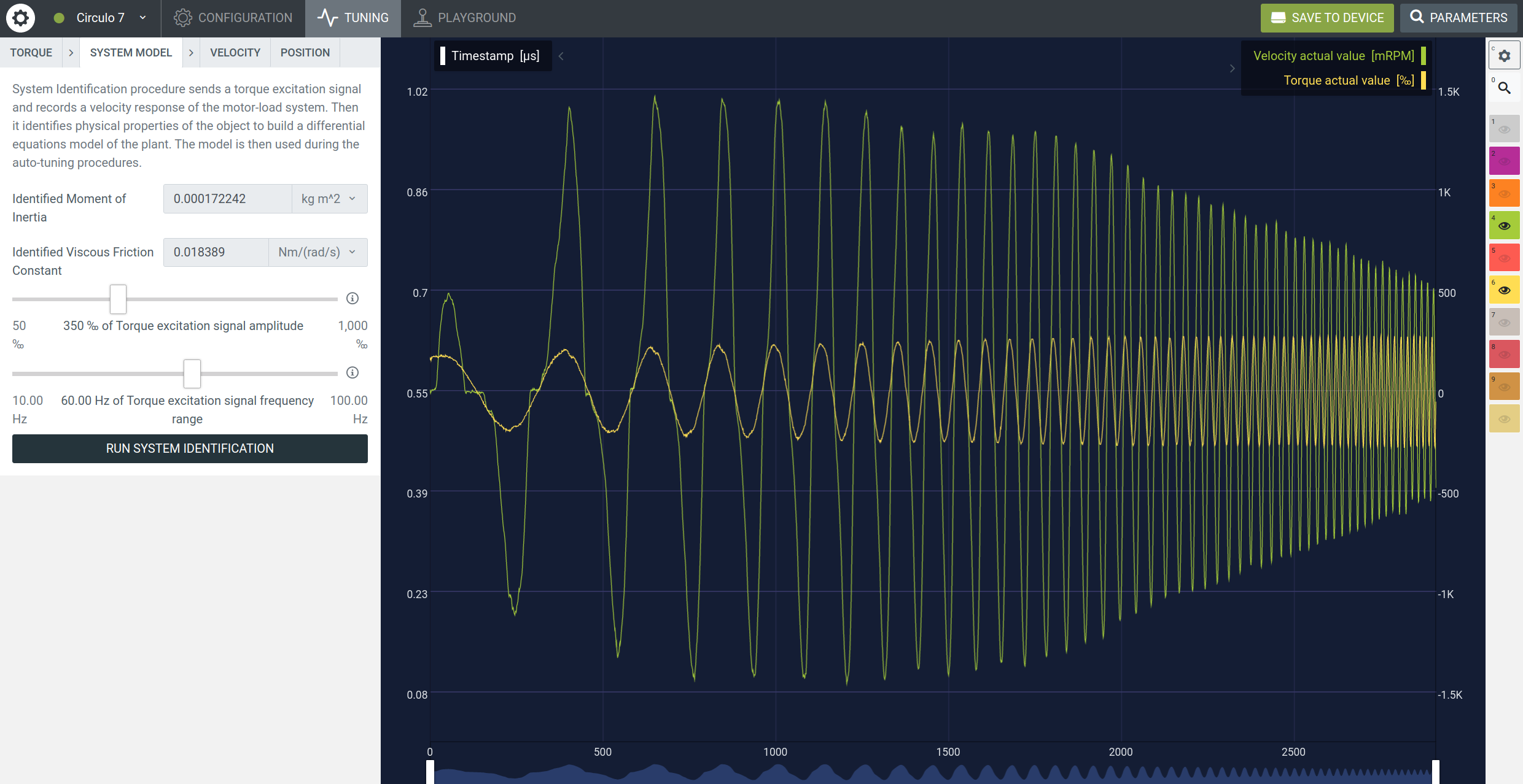
High values result in a better signal to noise ratio and allow to overcome static friction if the system doesn’t move with default input. However, oscillations may have a bigger amplitude and generate noise in the torque controller.
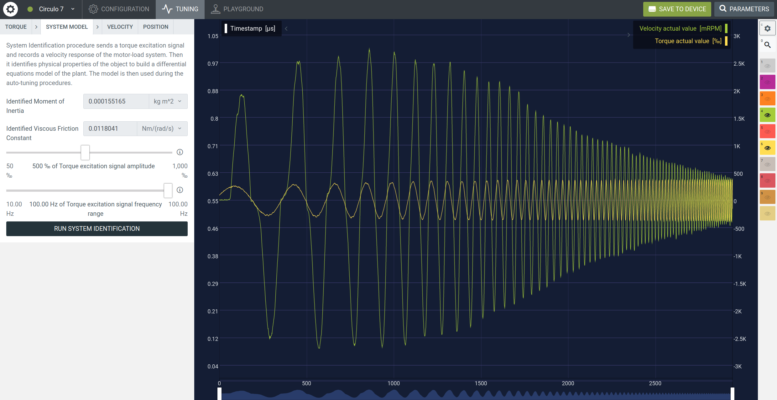
It is recommended to use the default value. Adjust the slider if a known resonance should be included into the model.
Low values will result in a more precise identification procedure and more stress on the mechanical structure.
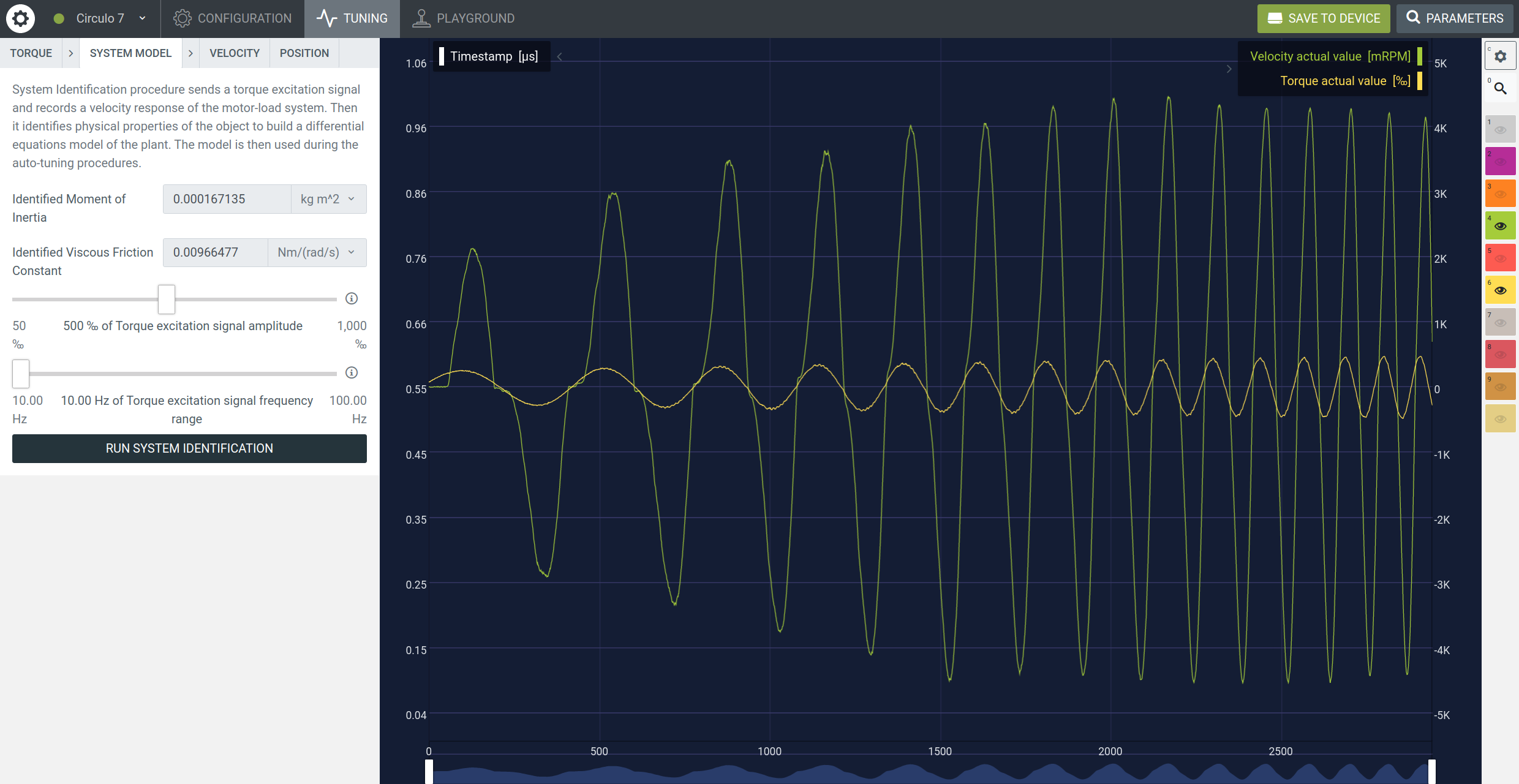
High values will result in less stress and the identification procedure will be less precise due to the EtherCAT communication delay. As a result, higher frequencies are included into the model. An example of high frequency range can be seen in the image below:
When the System Identification was successfully executed the dialog collapses to a button “Rerun System Identification”. A set of default controller gains is calculated and the options for position autotuning are displayed instead.
Note
If the electromechanical system was changed the identification should be repeated.
NEXT STEP: Position Autotuning
Calculate controller gains that result in a specified position control-loop performance.
NEXT STEP: Velocity Autotuning
Tune the velocity loop with Velocity Auto-Tuning for Cyclic Synchronous Velocity mode.
# Can I define other velocity/torque units in the custom firmware?
The system identification is possible only with default units.
# Do I have to repeat system identification after attaching a load to the system.
It is recommended to repeat the procedure.
# What if my encoder has a low resolution?
The velocity signal used in system identification might have multiple zeros that may result in an incorrect model.
# The system goes to overcurrent or the software resets during the system identification.
Check the configuration parameters and compare them to the official motor and sensor datasheet.
Ensure that the torque controller works correctly.
Lower the torque excitation signal amplitude.
