- Hardware Manuals
- Commissioning and Tuning Guide
- Software Reference
- Resources
The position control modes allow the EtherCAT master to send desired positions to the servo drive. The drive will make sure these position values are reached by the motor (if the motor is physically able to do so).
In this mode, the trajectory generator is located in the control device, not in the servo drive. In a cyclic synchronous manner, it provides a target position to the drive device, which performs position control, velocity control and torque control.
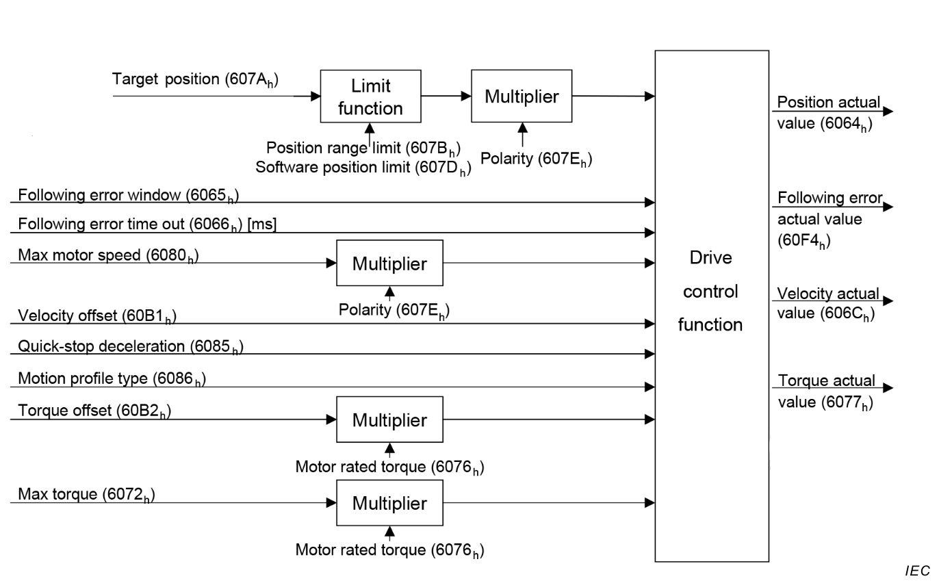
The figure above shows the inputs and outputs of the drive control function. The input values (from the control function point of view) are the target position as well as an optional velocity offset and an optional torque offset used for feed forward control. Especially in a cascaded control structure, where a position control is followed by a velocity or torque control, the output of the position control loop is used as an input for further calculation in the drive device. Limit functions can be used to restrict the range of values to avoid unintended positions. The drive device monitors the following error.
The target position is interpreted as absolute value. The position actual value is used as mandatory output to the control device. Further outputs are the velocity actual value and torque actual value. The following error actual value is used as an additional parameter. See Control supervision for details.
Three control loops are implemented for position control:
This mode uses some bits of the statusword for mode specific purposes which are indicated in yellow. The figure shows the structure of the statusword. For the general structure and usage, please refer to our Application note on Status- and Controlword.
The mode specific bits of the statusword can be used to monitor the performance of the operation. For further information please refer to the section on Control Supervision.
| 15-13 | 12 | 11 | 10 | 9-0 | ||||
|---|---|---|---|---|---|---|---|---|
| N/A | Target position ignored | Internal limit active | Target reached | basic | ||||
Internal limit active:
Target reached: the bit is set to 1 if the actual position stays in the window of the target position ± position window for a duration of position window time.
Target position ignored: This bit is set if Target position (0x607a) is equal to Position demand internal value (0x60FC). It means that the user command is passed directly through as an input of the position PID controller.
However, if the Target position is limited by Software position limits, the limited value will be used as an input of the PID controller and the bit will be cleared.
Note
0 = Target position ignored1 = Target position shall be used as input
Values Kp, Ki and Kd for Torque Controller
Values Kp, Ki and Kd for Cascaded Position Controller (Both loops: Position and Velocity)
Use this object to directly select a Target position
Sets a feed-forward velocity as input to the velocity controller.
Sets a feed-forward torque as input to the velocity controller.
