- Hardware Manuals
- Commissioning and Tuning Guide
- Software Reference
- Resources
Important
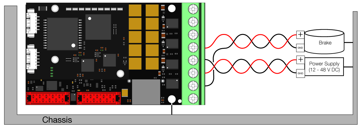
The cable length for Main Power Supply (12-48 V) must not exceed 30 m.

Important
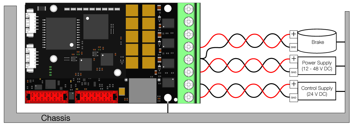
The power cables must be twisted for EMC reasons.
Attention
No reverse polarity protection! Always ensure that the power cables are connected correctly, otherwise the Drive may be damaged beyond repair!
Terminal # |
|
|---|---|
1 |
Phase A |
2 |
Phase B |
3 |
Phase C |
4 |
Phase D - Brake output 0-48 V PWM |
5 |
Ground |
6 |
Main Power Supply 12-48 V |
7 |
Optional Logic Ground * |
8 |
Optional Logic Supply 12-24 V ** |
* Maximum current carrying capacity: 10 A
Note
Note
SOMANET servo drives are densely packed with high-performance components. Even at idle/torque off, several components such as power supplies, cause the servo drive to get warm, especially when it’s not connected to any heat conducting structure. The servo drives’ power stages and control algorithms were optimized for efficiency at high power output and actually make them one of the most efficient servo drives available. The heat generation is not linear, which makes it actually more noticeable at idle or low power. Please ensure by design of your mounting situation that the heat interface is connected to sufficient structure to appropriately dissipate generated heat.
The indicated minimal supply voltage of 10 V is enough to power on the servo drive for configuration but for turning a motor, a voltage above 12 V is required.
Note
Due to voltage drop from power supply to the servo drive is it not recommended to supply the servo drive at absolute minimal voltages. If your system does not run at 12 V, increasing this value slightly may be necessary.
It’s recommended to use a protected extra-low voltage supply (PELV) instead of a safety extra-low voltage supply (SELV).
If a SELV is used, it’s possible that the isolation from the earth can be violated through our drive (e.g. through heatsink or mechanical mountings) and the supply becomes PELV.
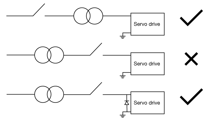
Attention
Our servo drives are designed for voltages between 24 V DC and 48 V DC (55 V DC; Max,cont 60 V DC Max,peak), they should be run with an appropriate extra-low voltage supply. Please do not use contactors behind the power supply since the transient-voltage-suppression diodes could get damaged due to the power-up voltage increase (Surge). This is likely to happen when the power up occurs fast and can lead to complete failure of your servo drive.
If contactors behind the power supply are used, it’s necessary to include an uni-directional TVS diode type 1.5KE62A-E3/54* between Main Power Supply and Ground of the terminal.
* this model has been successfully tested by Synapticon. Other products with the same specifications may also be appropriate but can’t be recommended.
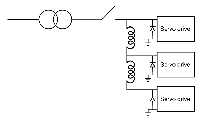
In case you are running several servo drives behind a contactor, please use an uni-directional TVS diode on each drive because of the inductances of the wiring.
Attention
When using a safe brake in combination with Node Safety, use SBC Out instead of Phase D.
If your system has an attached brake, please connect the brake cables to Phase D and Ground. These two threads should be twisted together or at least be paired to have a minimum area between them.
By default, Logic Supply is deactivated, it is therefore recommended to use Logic Ground (pin 7 of the Main Supply Connector) for the brake.
If Logic Supply is active, Ground of the brake can be connected to the Ground cable of the 48V power supply in a spot close to the board or it can be connected together with the Ground of the 48V supply to the pin 5 of the Main Supply connector if they fit in there.
Important
Please make sure the servo drive is properly grounded. You can connect the heatsink to ground.
