- Hardware Manuals
- Commissioning and Tuning Guide
- Software Reference
- Resources
Earthing is an electrically conductive connection to the earth. Earthing helps to cope with electromagnetic interference (EMI) and should always be considered.
A differentiation can be made between functional earthing (FE) and protective earthing (PE), which is additionally related to electrical safety.
Note
In Extra-Low-Voltage devices such as SOMANET Drives, protective earthing is not required but functional earthing is essential to cope with EMI issues.
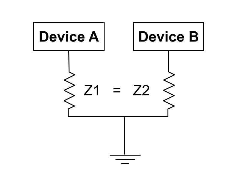
An earthing system (UK and IEC) or grounding system (US) is a common and standardized way to keep the potential of a system to the same level.
Earthing or grounding is the process of transferring the immediate discharge of electricity directly to the earthing plate with low resistance electrical cables or wires. It facilitates a physical connection between the ground and the electrical equipment and ensures the same voltage potential.
Electricity has two hazards which occur when an electric current passes through a person: thermal and shock risk.
Electrical current can be life-threatening above 25 mA in AC and 50 mA in DC. The resistance of the human body is generally between 1 kΩ - 5 kΩ. Assuming a human body has a resistance of 2 kΩ, the dangerous voltage can be calculated as 50 V AC or 120 V DC .
An earthing system (UK and IEC) or grounding system (US) affects the system’s safety and the electromagnetic compatibility (EMC).
Protective earthing is a type of earth used to protect people and animals from electric shocks and is effective in the event of a fault.
Protective earthing ensures on one hand that the user is at the same electrical potential as the device housing and on the other hand lets the fuse blow out of a short between phase and ground.
This protects users from electrical shocks when a piece of electric equipment has an insulation failure.
When an insulation failure occurs, the current can pass through the earthing cable path that is more conductive than the human body. The images below show the safe and dangerous conditions with and without PE.
Functional earth or functional ground is essential to have a trouble-free operation.
Possible consequence when functional earth (FE) is not considered:
Damage to electronic devices by electrostatic discharge is possible
EMC issues such as ground loops, random system behavior
Incorrect reading of the feedback devices that can cause control problems
Communication problems and loss of data or synchronization.
Interference to surrounding circuits near the servo drive system.
Compliance with Electromagnetic Compatibility (EMC) standards and directives may not be given.
SOMANET Drives are in the Extra Low Voltage (ELV) category. ELV voltage range is not life-threatening.
According to the standard for Adjustable speed electrical power drive systems (IEC 61800-5-1:2017), devices with an input voltage lower than 25 V:sub:AC and 60 V DC are in the DVCA category.
Note
PE connection is not required for the DVCA category.
ELV devices are usually fed by batteries or switching power supplies.
In some cases an earth connection can not be used, for example in mobile robotics.
Switching power supplies are widely used as a DC source for many applications in the ELV range.
Three categories of switching power supplies can be distinguished that are applicable for servo drives: PELV, SELV or FELV. They differ in their isolation:
FELV (Functional Extra Low Voltage): No special insulation is required. The load is not isolated by grounding.
PELV (Protected Extra Low Voltage): Special isolation is required. The load is not isolated by grounding.
SELV (Separated or Safety Extra Low Voltage): Special isolation is required. The load is isolated by grounding.
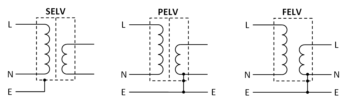
PELV is usually sufficient to meet the requirements. SELV is used where extra isolation is required (e.g. swimming pools).
Attention
SELV power supply can be violated if the equipment is using a common DC bus.
Table below shows the connection between the heat sink and V- which defines the earth connection.
Product |
V- and Chassis |
Note |
|---|---|---|
Circulo 7 and 9 |
Isolated |
|
Node 400,1000,2000 |
Not isolated |
V- is connected to the chassis directly. |
Braking chopper |
Isolated |
Because the mounting holes are connected to the V- plane in the PCB, the isolation will break when a conductive Spacer is used between the mounting holes on the PCB and chassis. This can violate an existing earthing system and if a SELV power supply is used it may become PELV. |
The drives generate a large amount of noise because high currents are switched.
In many use cases, the Motor enclosure is connected to a conductive part of a machine. The parasitic capacitor of the motor is always an alternative pathway which causes common mode noise issues.
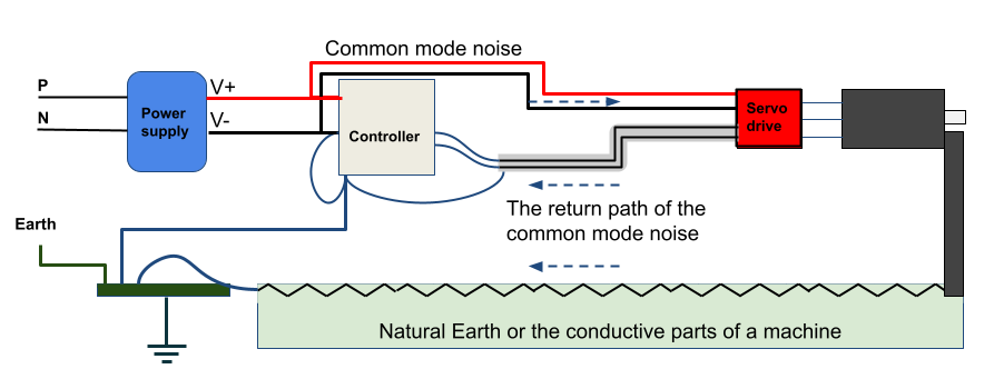
The image below shows an improper grounding. In this connection, there is no reliable connection from the motor enclosure to the earth. In this circuit, the noise passes through the shielding and natural earth. The earth impedance on the motor side (power side) is higher than on the control side, which causes a ground loop issue.
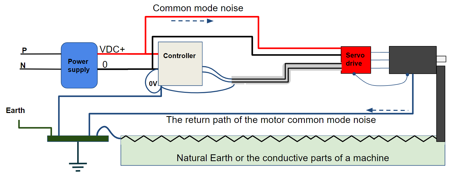
In the next drawing, the motor is connected directly to a low impedance FE with a proper earth connection. In this circuit, the noise passes through the earth cable.
The shielding is connected to the earth correctly, and there is no ground loop because of the unbalanced impedance.
A low impedance earth connection is essential to have less EMI issues. For example, daisy-chaining will increase the EMI issues and ground loops because of the unbalanced ground impedance.
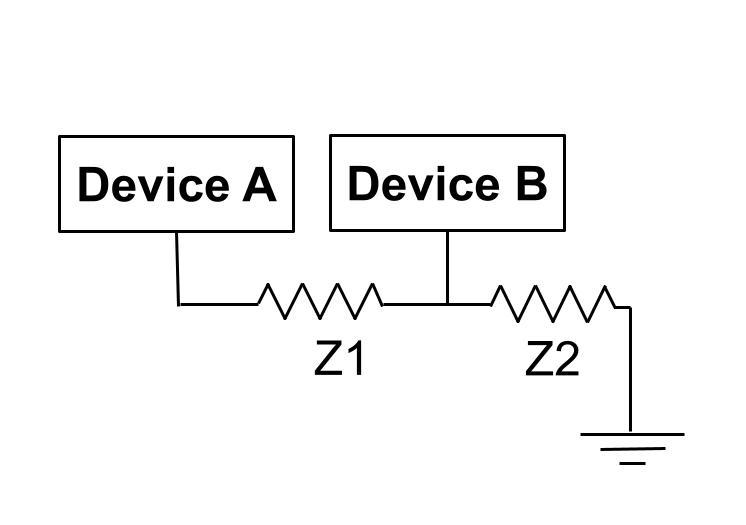
Using a star connection for earthing will result in a better grounding balance and fewer issues with the ground loop and EMI.