- Hardware Manuals
- Commissioning and Tuning Guide
- Software Reference
- Resources
Important
The motor and power cables must be twisted for EMC reasons.
Attention
No reverse polarity protection! Always ensure that the power cables are connected correctly, otherwise the Drive may be damaged beyond repair!
Note
SOMANET servo drives are densely packed with high-performance components. Even at idle/torque off, several components such as power supplies, cause the servo drive to get warm, especially when it’s not connected to any heat conducting structure. The servo drives’ power stages and control algorithms were optimized for efficiency at high power output and actually make them one of the most efficient servo drives available. The heat generation is not linear, which makes it actually more noticable at idle or low power. Please ensure by design of your mounting situation that the heat interface is connected to sufficient structure to appropriately dissipate generated heat.
Note
Use a protected extra-low voltage (PELV) power supply.
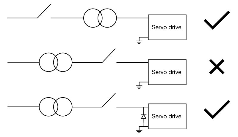
Attention
Our servo drives are designed for voltages between 24 V and 48 V (60 V Max), they should be run with an appropriate extra-low voltage supply. Please do not use contactors behind the power supply since the transient-voltage-suppression diodes could get damaged due to the power-up voltage increase (Surge). This is likely to happen when the power up occurs fast and can lead to complete failure of your servo drive.
If contactors behind the power supply are used, it’s necessary to include an uni-directional TVS diode type 1.5KE62A-E3/54* between Main Power Supply and Ground of the terminal.
* this model has been successfully tested by Synapticon. Other products with the same specifications may also be appropriate but can’t be recommended.
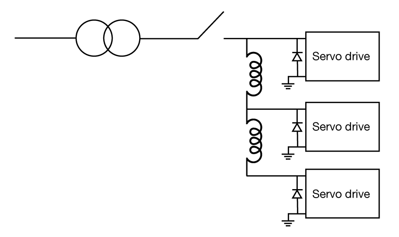
In case you are running several servo drives behind a contactor, please use an uni-directional TVS diode on each drive because of the inductances of the wiring.
Functional Earth (FE) and the Ground (GND) of the electronic boards are electrically isolated.
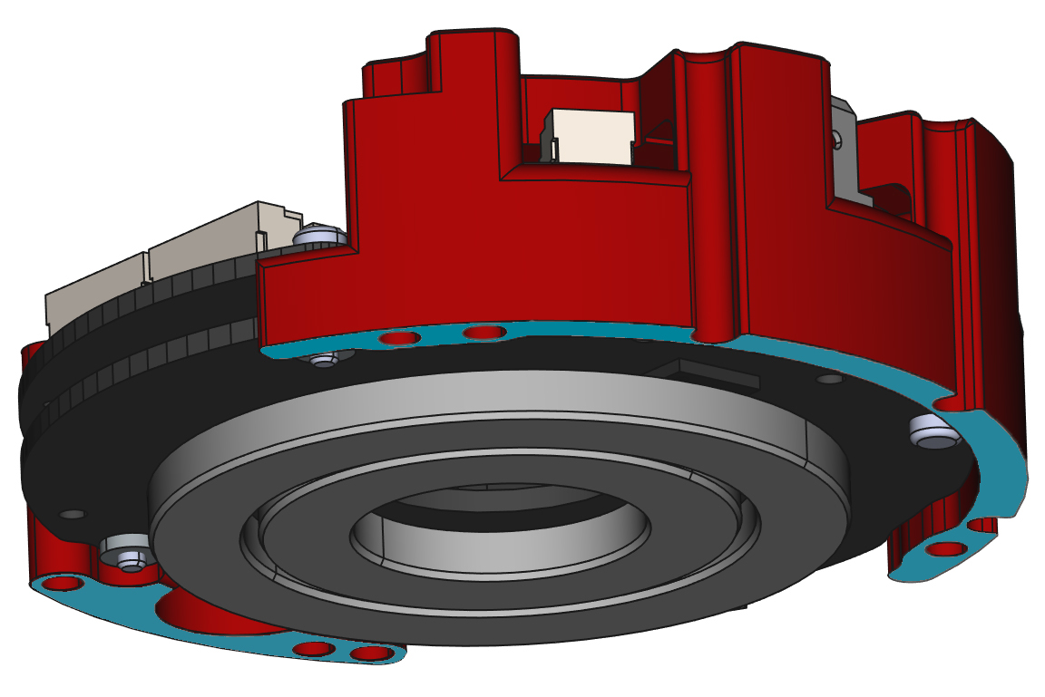
The blank bottom side of the heatsink has a flat conductive surface and can be used as a connection for Functional Earth (FE).
For a better EMI shielding around the electronic boards, it is necessary to electrically connect the conductive surfaces (marked blue in the following picture) to the chassis of the motor or the robot.
Important
Please ensure that the chassis is properly grounded.
Note
Protective Earthing is not required for Extra-Low Voltage Drives.
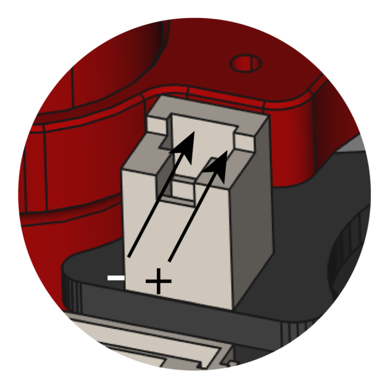
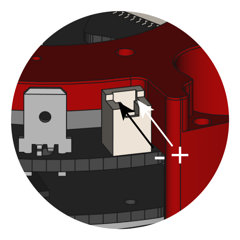
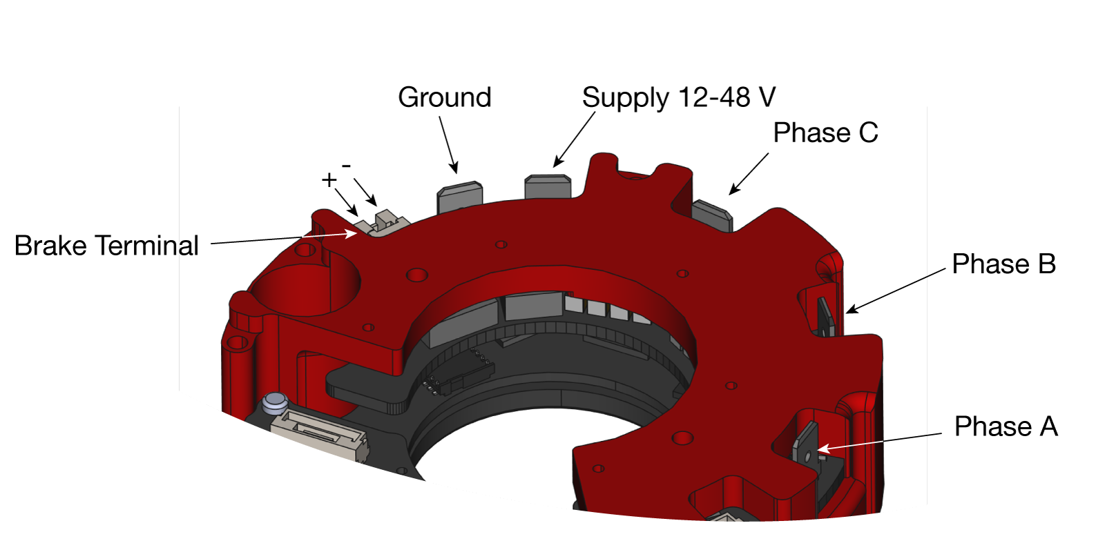
If your system has an attached brake, please connect the brake cables to the brake connector. These two threads should be twisted together or at least be paired to have a minimum area between them.
Note
This brake integrates Safe Brake Control functionality (SBC).