- Hardware Manuals
- Commissioning and Tuning Guide
- Software Reference
- Resources
These filters are used to cope with distorted feedback signals that occur in the control loop. Typical distortions to consider are:
Encoder noise in the position signal - optical and good magnetic encoders usually have a low amplitude. 1st order filters with a 1000 Hz 1 cutoff are a good starting point.
Noise in the velocity signal - noise from the position signal is amplified due to differentiation. 1st order filters with a 500 Hz * cutoff are a good starting point.
Velocity signal distortions due to encoder nonlinearity. These distortions typically appear with a frequency of 1 (dominant), 2 and 4 ꞏ motor speed [revolutions per seconds].
The specified frequencies are just initial values that will not interrupt the motion control. Lower values should be found and set see A practical guide to low-pass filter design
Note
Setting the velocity filter more rejective than the position filter is one possible approach, see A practical guide to low-pass filter design for details how to set up filter parameters.
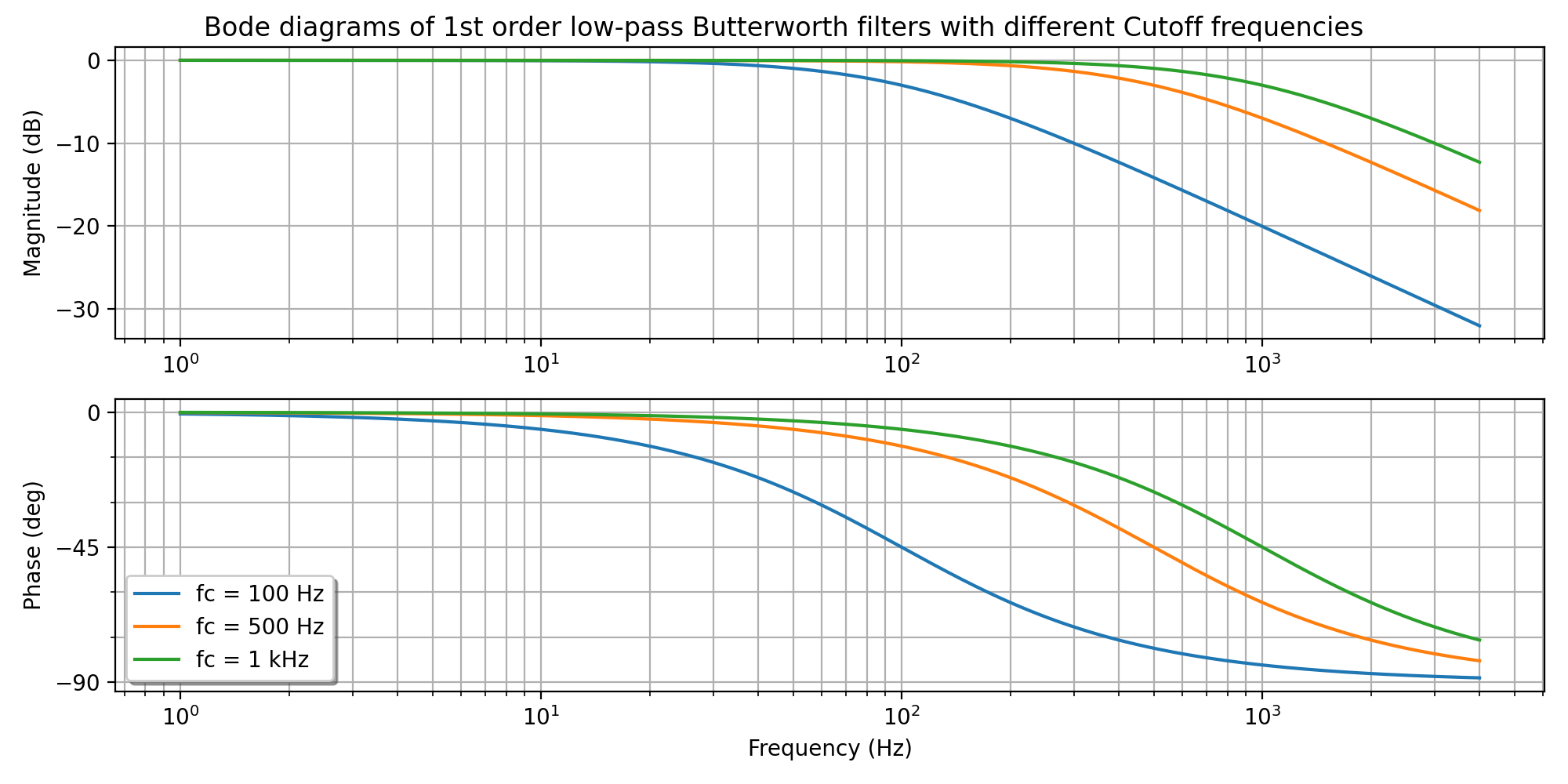
The main parameter of the Low-pass filters is the cutoff frequency which determines the frequency where the filter starts to attenuate the signal to -3 dB of the amplitude. After that frequency, a roll-off region starts that further attenuates the signal.
Note
Filtering comes at a cost of a phase shift. This might significantly limit the maximum sharpness of the control loop.
Determine the approximately required bandwidth of the control loop. This can be done based on the reference profile specifications or roughly estimated from the actual rise time during a step response test:
Ideally, the filtered signal shouldn’t be modified until this frequency. The magnitude change and phase shift caused by the filter have to be as little as possible. Thus, the filter cutoff frequency should be approximately one decade higher (Bw ꞏ 10).
Examine the spectral density plot of the target signal and determine the frequency range that has to be filtered out.
Enable a filter with the default cutoff frequency.
Try to change the cutoff frequency until an appropriate balance between noise filtering and phase-shift/magnitude attenuation is reached.
0x2021 Velocity feedback filter
Cut-off frequency of velocity feedback filter
0x2022 Position feedback filter
Cut-off frequency of position feedback filter

![Bw \simeq \frac {0.35} {t_r} [Hz]](../../../../../../_images/math/6b5e2e3f8d3314bb6b1d5b9cf8246ee668602ddb.svg)