- Hardware Manuals
- Commissioning and Tuning Guide
- Software Reference
- Resources
Note
Details about measuring Analog signals can be found in our system integration guideline: Connecting and configuring analog inputs
Pin # |
Signal |
|---|---|
1 |
Differential +5 V |
2 |
Differential -5 V |
3 |
Ground |
4 |
Single-ended 0-10 V |
5 |
+5 V* |
6 |
+10 V** |
Supported Encoders |
Config. 1 * |
Config. 2 |
Config. 3 |
Config. 4 |
Config. 5 |
|---|---|---|---|---|---|
Internal Encoder 1 |
BiSS |
BiSS |
|||
Internal Encoder 2 |
BiSS |
Disabled |
|||
External Encoder |
ABI (Differential or Single-Ended) or HALL |
BiSS (Differential) |
SSI (Differential) |
Half-Duplex/A-Format (Differential) |
ALL |
* Only 2 out of the 3 Encoders can be used at the same time.
Pin # |
ABI (Differential) |
ABI (Single-Ended) |
BiSS (Differential) |
SSI (Differential) |
Half-Duplex/A-Format (Differential) |
HALL |
|---|---|---|---|---|---|---|
1 |
MA- |
Clock- |
SD- / A |
|||
2 |
5 V |
5 V |
5 V |
5 V |
5 V |
5 V |
3 |
Ground |
Ground |
Ground |
Ground |
Ground |
Ground |
4 |
MA+ |
Clock+ |
SD+ / B |
|||
5 |
A- |
A |
SLO- |
Data- |
H3 / C |
|
6 |
A+ |
SLO+ |
Data+ |
|||
7 |
B- |
B |
H2 / B |
|||
8 |
B+ |
|||||
9 |
I- |
I |
H1 / A |
|||
10 |
I+ |
Pin |
GPIO |
Logic level |
REM 14/16MT |
BiSS (LVTTL) |
SSI (LVTTL) |
SPI |
|---|---|---|---|---|---|---|
1 |
3.3 V * |
3.3 V * |
3.3 V * |
3.3 V * |
3.3 V * |
3.3 V * |
2 |
Digital IO 1 |
Configurable as 3.3 V or 5 V |
SCK |
SLO |
Data |
SCK |
3 |
Digital IO 2 |
Configurable as 3.3 V or 5 V |
MISO |
MA |
Clock |
MISO |
4 |
Ground |
Ground |
Ground |
Ground |
Ground |
Ground |
5 |
Digital IO 3 |
Configurable as 3.3 V or 5 V |
MOSI |
MOSI |
||
6 |
Digital output 4 ** |
Configurable as 3.3 V or 5 V |
SS |
SS |
||
7 |
5 V *** |
5 V *** |
5 V *** |
5 V *** |
5 V *** |
5 V *** |
8 |
Digital IO 5 |
Configurable as 3.3 V or 5 V |
||||
9 |
Digital IO 6 |
Configurable as 3.3 V or 5 V |
||||
10 |
Digital input 7 |
24 V |
Note
Note
Pin # |
Signal |
|---|---|
1 |
STO/SBC1 input 1 |
2 |
STO/SBC2 input 2 |
3 |
Safety Ground |
4 |
FE |
5 |
STO/SBC Feedback + |
6 |
STO/SBC Feedback - |
Wiring diagrams for the safety digital inputs
Attention
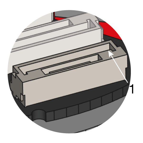
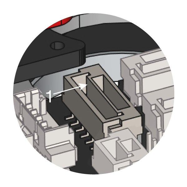
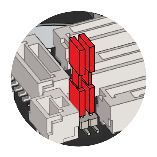
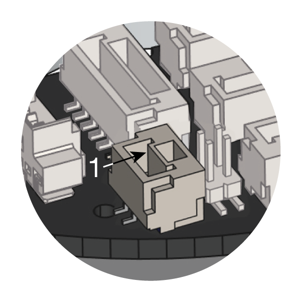
When not using the STO-SBC feature, the function must be bypassed by bridging the jumpers:
Pin # |
Signal |
|---|---|
1 |
+V_BAT |
2 |
Ground |
For selecting a suitable battery, please check these notes.