- Hardware Manuals
- Commissioning and Tuning Guide
- Software Reference
- Resources
The manual describes how to tune the cascaded position controller using the Auto-tuning feature.
Before conducting any of the tuning activities please check if motor is functional in torque mode and sensor data is transmitted normally. For high-quality motor control tasks, a precise and reliable sensor should be used. Quality of the motor position control may be insufficient with low resolution sensors, especially if a Hall sensor is used.
The current version of the auto-tuning feature allows user to tune a BLDC motor drive. A load can be attached to the motor. However, if the motor position has very strict limits this feature is not recommended, because the motor may make a few full turns.
Auto-tuning is performed in two steps:
System identification Identifying the physical properties of the object to build a mathematical model of the target system.
Depending on the application, either position or velocity Auto-tuning can be performed:
Position auto-tuning Using the model to calculate controller gains that result in a specified position control-loop performance.
Velocity auto-tuning Tuning the velocity loop with Velocity Auto-Tuning for Cyclic Synchronous Velocity mode (CSV) or Profile Velocity Mode (from firmware 4.2 on).
The Position Auto-tuning process calculates the gains for the cascaded controller automatically.
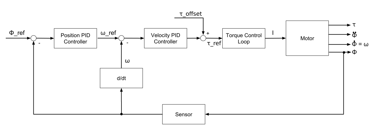
The core of the cascaded controller is linear. However, there are multiple nonlinear additions: saturation, feedforward terms and integrator clamping.
Note
In our experience, the cascaded PID controller structure is one of the most effective for motor control applications. For details see PID Controllers: Theory, Design, and Tuning
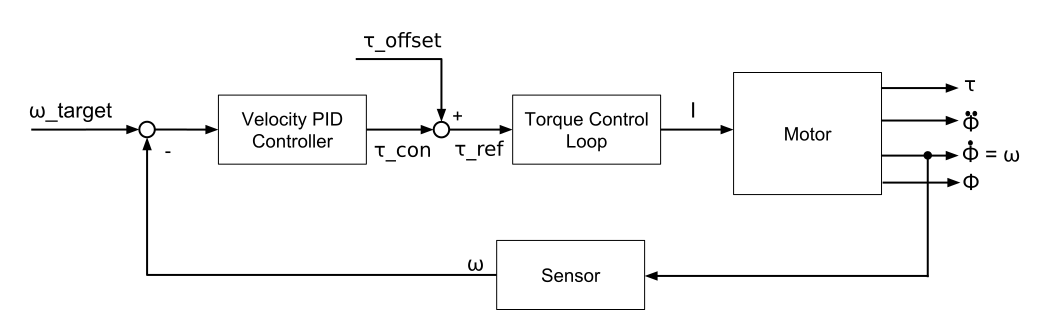
The Velocity Auto-tuning process calculates the gains for the velocity controller automatically.