- Hardware Manuals
- Commissioning and Tuning Guide
- Software Reference
- Resources
When the drive is in motion and the user wishes to stop quickly for any reason, the Quick Stop state can be activated. This function uses a profile to drive the motor from the current velocity down to zero with a specific Quick Stop deceleration. Quick stop can also be performed when an internal fault happens to stop the drive in a controlled way.
Attention
Note that the brake might get damaged when the motor does not ramp down to zero velocity. This can happen due to one of the following reasons:
when the motor is mechanically unstable
when the control system is unstably or poorly tuned
when the quick-stop feature is misconfigured
If no brake exists, this can even lead to a damaged motor!
Note
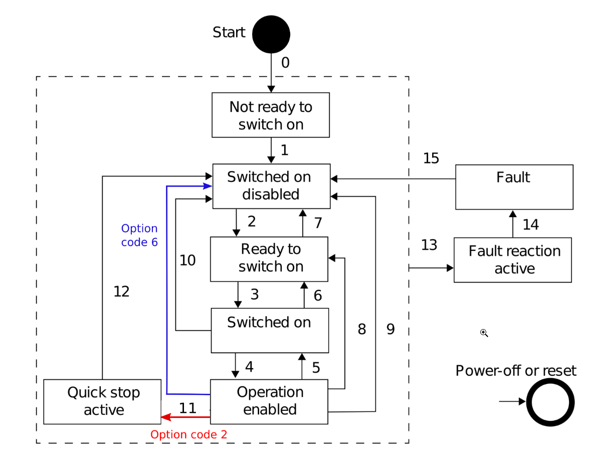
At the end of the quick stop procedure, the brake gets engaged when the drive is in SWITCH_ON_DISABLED (mode 2). When the drive stays in QUICK_STOP_ACTIVE (mode 6) the brake is not engaged by default.
Quickstop will be enabled if one of the following conditions occurs:
Bit 2 (quick stop bit) of the Controlword changed from 1 to 0 (transitions 7, 10, 11 according to the drive state machine diagram.
A drive fault is triggered
The drive dropped from EtherCAT Operational state while it was in CiA402 Operational Enabled state
Object 0x605A Quick stop option code has different options that switch the drive into different states:
Option code |
Definition |
|---|---|
0 |
Disable drive function (no quick stop deceleration) |
2 (default) |
Slow down on quick stop ramp and transit into switch on disabled |
6 |
Slow down on quick stop ramp and stay in quick stop active |
The execution of the procedure depends on the operational mode that is active:
In position control modes (Cyclic Synchronous Position mode, Profile Position mode, Cogging recording, Homing) the quick stop procedure uses the position controller to stop the motor.
In velocity control modes (Profile velocity mode, Cyclic Synchronous Velocity Mode), the quick stop procedure uses the velocity profiler to stop the motor.
During the procedure, torque offset can be used to compensate for possible torque from the load.
The steps vary depending on the quick stop option code and when quick stop is triggered:
Attention
In this case, the drive does not perform the quick stop deceleration ramp and is instead immediately disabled.
The Drive commands a quick stop ramp that ramps down an effective commanded velocity according to the user-defined quick stop deceleration.
The end of the quick stop ramp is a moment when the commanded velocity is equal to 0.
A timeout period of 100 ms is started in which the drive commands a fixed position or zero velocity.
After the end of the quick stop ramp, the drive is disabled, which automatically engages the brake as defined by the brake settings.
The Drive commands a quick stop ramp that ramps down an effective commanded velocity according to the user-defined quick stop deceleration.
The end of the quick stop ramp is a moment when the commanded velocity is equal to 0.
After the end of the quick stop ramp, the drive continues to stay in Quick Stop Active until a command to disable the drive is received. In position control modes (Cyclic Synchronous Position mode, Profile Position mode, Cogging recording, Homing), Quick Stop Active drive keeps the current position.
In velocity control modes (Profile velocity mode, Cyclic Synchronous Velocity Mode), the drive controls 0 velocity.
Attention
The brake is not engaged by default in this state.
In torque modes (Cyclic Synchronous Torque mode, Profile torque mode) the quick stop procedure does not use a profile. Instead, the drive commands 0 torque from the start of the quick stop procedure. The steps vary depending on the quick stop option code and when quick stop is triggered:
Note
In this case, the drive does not perform the quick stop deceleration ramp and is instead immediately disabled.
The Drive commands Target and offset torque
At the same moment, the timeout period starts. The timeout period is calculated as actual motor velocity divided by the quick stop deceleration. In this way, a user can configure the maximum duration of the quick stop procedure.
During the timeout period, the drive monitors if the drive reaches zero velocity
The brake gets engaged and the drive is set to state Switch On Disabled, if one of the conditions are true:
The actual velocity of the motor reached 0
The timeout period has expired
The Drive commands Target and offset torque. According to the DS 402 standard, the drive remains in the torque control mode it was triggered from.
The drive continues to stay in Quick Stop Active until a command to disable the drive is received.
Note
When quick stop is commanded during Offset detection, the procedure is aborted and the drive is disabled.
Select the action that is performed when the quick stop function is executed.
0x6085 Quick stop deceleration
Defines the quick stop ramp
Shows the drive’s transition into a different state. Use this object to monitor the drive’s behavior.
This object defines the velocity value
0x60FC Position demand internal value
Provides the output of the trajectory generator in profile position mode.
Provides the actual value of the position encoder.
Output of position controller in position mode/trajectory generator in velocity mode.
Provides the value read at the velocity sensor (or the derivation of the position signal).
Provides the output value of the torque trajectory generator.
Provides the actual value of the torque.
