- Hardware Manuals
- Commissioning and Tuning Guide
- Software Reference
- Resources
Attention
Digital input STO-SBC 1 |
Digital input STO-SBC 2 |
Internal fault |
Safety Statusword |
Error entry |
|---|---|---|---|---|
0 |
0 |
no |
1 |
|
0 |
1 |
no |
1 |
“SfeDilvd” |
1 |
0 |
no |
1 |
“SfeDilvd” |
1 |
1 |
no |
0 |
|
0 |
0 |
yes |
1 |
“SfeFault” |
The safety circuit has two integrated diagnostic functions:
Comparing safety digital input statuses. The fault is activated after 100ms discrepancy of the STO-SBC inputs. In case a fault is detected, the servo drive will enter Fault state and indicate a fault “SfeDilvd” in the Error Report object.
During the activation of the STO-SBC function the servo drive verifies that the two channels of the module are internally operating correctly. In case an internal fault is detected, the servo drive will enter Fault state and indicate a fault “SfeFault” in the Error Report object.
In case a fault has been detected, the drive will stay in fault state until manual reset has been given and the brake is closed.
To reset a fault condition, please:
request STO/SBC (for example by activating the emergency stop device) and
reset the fault
Attention
When the fault resetting was not successful, power cycle the servo drive and investigate the reason for the failure.
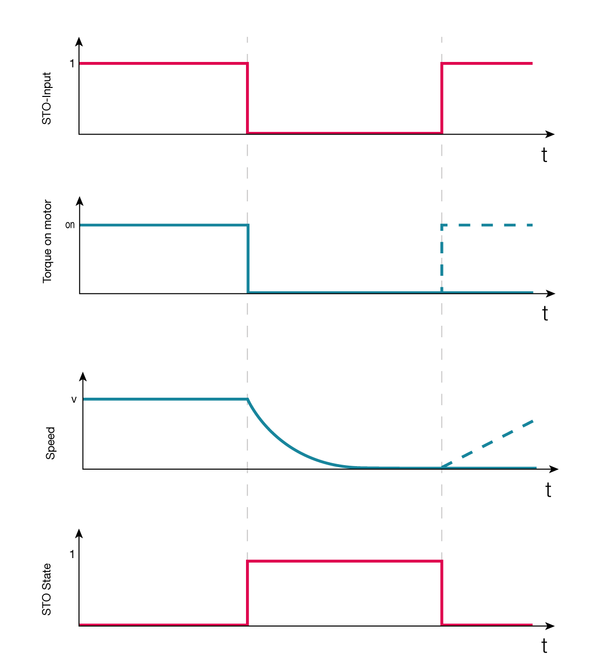
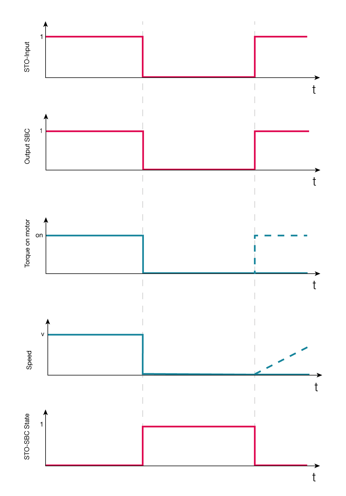
The Safety Statusword indicates the current state of safety functions and Safety Digital Input Diagnostics shows the state of the Safety Module inputs.
Index |
Name |
Descriptions |
|---|---|---|
0x6621 |
Safety Statusword |
Subindex:
STO/SBC status:
|
0x2611 |
Safety Digital Input |
Subindex:
Input 1/2:
|
Important
Using the SBC function while running the motor may damage the brake due to mechanical stress. During normal operation it is recommended to activate STO-SBC after the motor has come to a halt e.g. by introducing a delay with an external safety logic device such as a safety timer. This way an equivalent of SS1 with time monitoring is implemented.
Attention
The STO-function does not provide electrical isolation from the mains supply. If electrical changes need to be carried out on the system (e.g. modifying the motor cabling), the servo drive shall be completely isolated from mains supply with a mechanical switch.
