- Hardware Manuals
- Commissioning and Tuning Guide
- Software Reference
- Resources
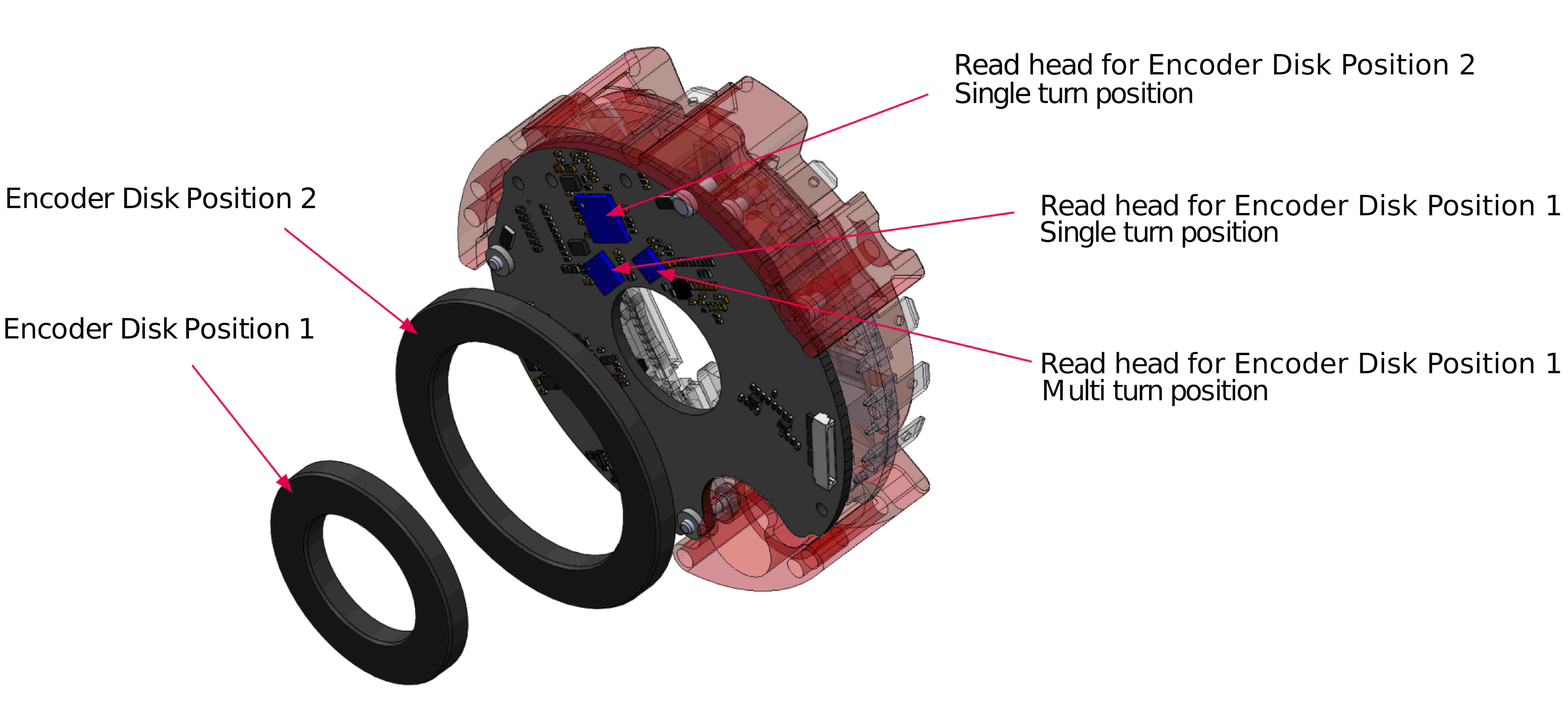
SOMANET Circulo optionally features one or two integrated encoders.
The Encoders must be calibrated before putting the system into operation.
Attention
In OBLAC Drives (via Virtual Machine) the Encoder calibration can only be performed in versions 20.2.6 and higher.
Note
Set up OBLAC Drives
Check the current version of OBLAC Drives (requires 20.2.0 or higher)
Install the latest firmware before commissioning
Configure your setup
Run Offset Detection
Perform System Identification
Perform Velocity Tuning
This set of features allows to:
Check the distance between the chip and the magnetic target
Detect mounting eccentricity or encoder ring wobbling
Validate if the encoder system is fully functional
Read error states directly from the encoder chip
This feature estimates the distance between the encoder chip and the magnetic target at the current position. The provided values should be used as an additional information source, not as primary mounting instructions. Due to properties of the magnetic field sensors, the actual accuracy can be up to 0.2 mm.
Performs a diagnostic test of the encoder system. One rotation of the currently selected encoder will be done in the open-loop field control mode. The obtained data will be used to compute a distance map over a full revolution. This is helpful to detect distance variations and hence mounting eccentricity or encoder ring wobbling.
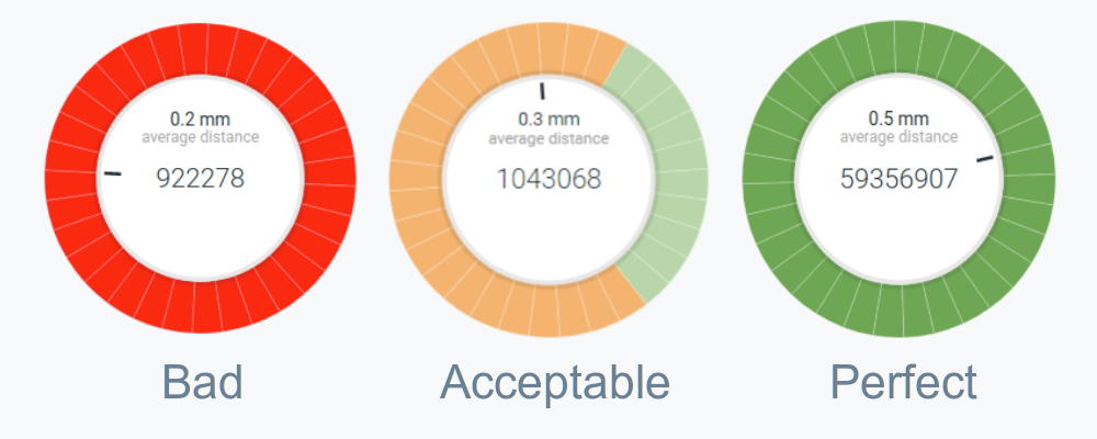
If you observe a pattern similar to the middle image above after running the CHECK ENCODER SYSTEM, consider checking the quality of the encoder ring assembly.
This command establishes a direct communication with the encoder chip and the Multiturn counter (if configured). Error registers are read and displayed:
Name |
Description/remedy |
|---|---|
Startup error |
Encoder initialization error. Power cycle the drive, connect the multiturn battery (if multiturn is used). |
Signal error: clipping (nonius track) |
A magnetic ring is too close to the encoder chip. Check the mechanical assembly. |
Signal error: poor level (nonius track) |
A magnetic ring is too far from the encoder chip. Check the mechanical assembly. |
Signal error: clipping (master track) |
A magnetic ring is too close to the encoder chip. Check the mechanical assembly. |
Signal error: poor level (master track) |
A magnetic ring is too far from the encoder chip. Check the mechanical assembly. |
Excessive signal frequency for internal 12 Bit converter |
Encoder maximum speed is exceeded. |
Excessive signal frequency for ABZ-converter |
Encoder maximum speed is exceeded. |
Period counter consistency error: counted period ↔ calculated Nonius position |
Phase error is too high. The absolute position can’t be computed reliably. Can be caused by changed mechanics, thermal expansion or magnetic target damage. Run diagnostics and repeat calibration. |
Multiturn data consistency error: counted multiturn ↔ external MT data |
Multiturn counter doesn’t work properly. Check if the MT battery is connected and power cycle the drive. |
Multiturn communication error |
The multiturn counter chip is in error state. Check the battery voltage and replace it if needed. |
I2C communication error: No EEPROM or I2C communication error |
Communication with the EEPROM memory of the chip is distorted. Power Cycle the drive. If this can’t be reset, there is a hardware problem. |
Attention
If two encoders are used, please calibrate encoder 2 (typically the motor shaft) first and then repeat the procedure for encoder 1 (typically the output shaft).
Download and install a special calibration version of the firmware
In order to reliably execute the calibration procedure, velocity should be tuned soft. Go to the velocity tuning section and set the Bandwidth slider up to 20 Hz (the changed parameters will not be saved to the Drive memory). Make sure the velocity control mode is functional by running some slow motion profile.
Use the CHECK ENCODER SYSTEM button to verify the current state of the encoder system:
The calibration requires mechanical rotation of the motor with an attached encoder.
Encoder |
Revolutions, speed |
|---|---|
Circluo 7, Encoder 1 (Inner ring) |
2 revolutions, 20 RPM |
Circluo 7, Encoder 2 (Outer ring) |
18 revolutions, 180 RPM |
Circluo 9, Encoder 1 (Inner ring) |
2 revolutions, 20 RPM |
Circluo 9, Encoder 2 (Outer ring) |
9 revolutions, 90 RPM |
Each iteration requires approximately 10 seconds.
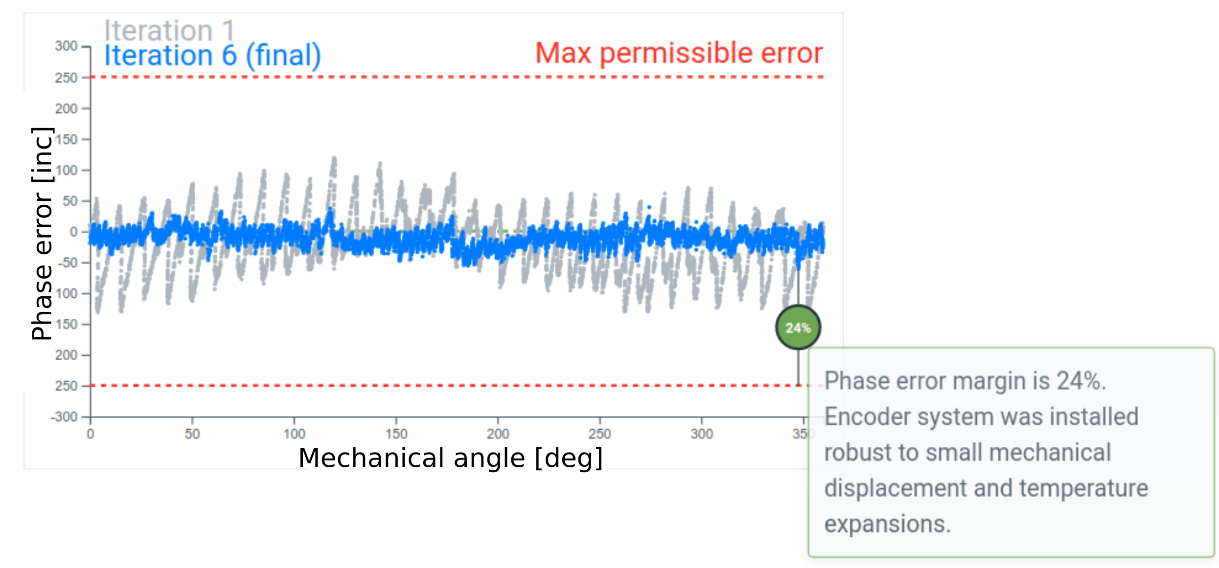
After the calibration procedure is done, check the estimated phase error plot. Note the resulting phase error margin. A smaller margin results in more robust behavior of the encoder system: small mechanical changes, vibration and temperature expansion are less likely to cause an error.
Attention
If the magnetic target was damaged mechanically or magnetically, this will be visible from the data as a single spike or an irregular error pattern.
After the optimal calibration parameters have been found:
Install the latest version of the firmware.
Run Offset Detection again to find your optimized offset.
Perform Velocity Tuning or Position Tuning (depending on the application).
Attention
The calibration procedure must be repeated when the mechanical position of the magnetic ring has changed. This can also occur when mechanical wear has impaired the system performance.
An error will be triggered during startup in the Error Report Object when the calibration is required again: BisErBit
