- Hardware Manuals
- Commissioning and Tuning Guide
- Software Reference
- Resources
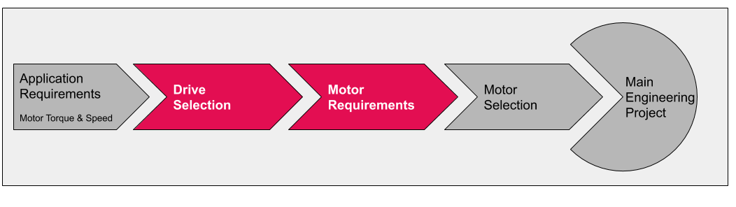
Selecting the correct motor and drive is an important task in any engineering project:
The system may be damaged if it’s not correctly dimensioned.
With an oversized system, your costs will be too high and your product won’t compete.
Only with a properly sized and matching set of motor and drive you can reach your speed and performance targets.
The selection highly depends on your application but it’s necessary to understand the different parts of the drivetrain:
Mechanical Power: P mech =  (Upper limit can be given by gearbox)
Practically simplified formula:
P mech =
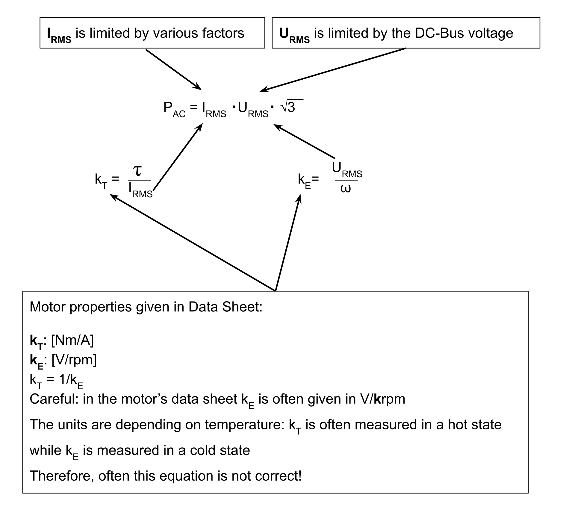
AC Power: P AC = I RMS ・ U RMS ・ 
U RMS ≤  ・ 𝛈 voltage
I RMS is limited |
by the Servo Drive |
by the Motor |
Note |
|---|---|---|---|
in continuous rated operation |
Continuous current |
Continuous current |
Thermal limit on any component that has to carry current. (FETs and motor windings) |
in continuous stall operation |
Continuous current |
Continuous stall current |
Similar thermal limit as in continuous rated operation. Since there are no iron losses here, the motor can stand a bit more. |
in max intermittent operation |
Max intermittent current |
Max intermittent current |
Max current can be applied for a short time only (e.g. 250 ms).
|
DC Power: P DC = U DC ・I DC
For selecting a drive, the maximum RMS phase current is the important parameter that should be considered. According to the technical specification table for a given servo drive and a known maximum RMS phase current, an appropriate drive can be chosen for the application. In case the peak current desired for the application is not explicitly known, it can be estimated assuming linear torque characteristics.
Maximum peak phase current =  ( + nonlinearity buffer)
For the peak torque, the maximum torque required in the application must be considered - which is not necessarily the peak torque that the motor can provide or its datasheet claims. As real motor characteristics are not linear, a buffer shall be added to the linearly calculated peak current. A buffer of 10% to 50% is reasonable, depending on how much the overload ![\big[ \frac {{\tau}_{peak}} {{\tau}_{rated}} \big]](../../../_images/math/721bc0ae42541efbef6e431a70c82efd63bcd529.svg) is. If the maximum torque required by your application does not exceed the rated torque of your motor (overload <= 1), a buffer of 10% in the equation above is fine. If the peak torque used in your application is 2, 3 or 4 times the rated torque of the motor, the motor can run into its saturation region, where bigger nonlinearity buffers can be required. For details, consult with the motor manufacturer and check the motor curves.
is. If the maximum torque required by your application does not exceed the rated torque of your motor (overload <= 1), a buffer of 10% in the equation above is fine. If the peak torque used in your application is 2, 3 or 4 times the rated torque of the motor, the motor can run into its saturation region, where bigger nonlinearity buffers can be required. For details, consult with the motor manufacturer and check the motor curves.

