- Hardware Manuals
- Commissioning and Tuning Guide
- Software Reference
- Resources
Assemble the Circulo with Internal encoders
Make sure the Encoder Rings are installed properly
Set up OBLAC Drives
Check the current version of OBLAC Drives (requires 20.2.0 or higher)
Install the latest firmware before commissioning
Configure your setup
Run Offset Detection, Perform System Identification. Perform Velocity Tuning
Alternatively, copy the configuration file from a similar actuator and perform the Offset Detection
Note
The Encoder Calibration tab will not be visible on Circulos that are part of an assembly (e.g. a robot joint that is delivered preconfigured and calibrated by a joint manufacturer).
Note
If you turn off the Circulo/OBLAC Box or disconnect the EtherCAT cable during the encoder calibration process, the internal EEPROM memory might have an invalid configuration and show a fault. You can overcome this problem by just repeating the calibration.
Note
If two encoders are used, please calibrate the motor shaft encoder first (typically encoder 2) and then repeat the procedure for the output shaft encoder (typically encoder 1).
Download and install a special calibration version of the firmware (x.y.z-calibration) which can be found in the Update firmware section of OBLAC Drives.
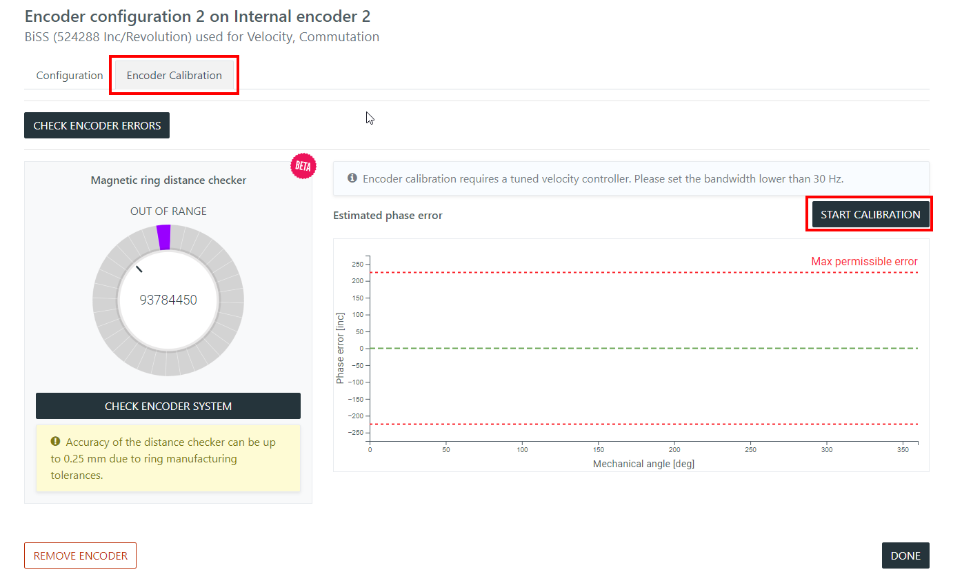
In order to reliably execute the calibration procedure, the velocity should be tuned softly. Go to the velocity tuning section and set the Bandwidth slider lower than 30 Hz (the changed parameters will not be saved to the Drive memory). Make sure the velocity control mode is functional by running some slow motion profile: the rotor doesn’t stop during motion and doesn’t vibrate due to overturning.
Go to the encoder configuration of the motor shaft encoder and open the Encoder Calibration tab.
The calibration requires mechanical rotation of the motor with an attached encoder (see table below).
The encoder will perform several revolutions in the positive direction and then will return to the original position. This will be repeated several times.
Each iteration requires approximately 10 seconds.
Motion during calibration:
Encoder |
Revolutions, speed |
|---|---|
Circulo 7, Internal encoder 1 (Inner ring) |
max 2 revolutions,15 RPM |
Circulo 7, Internal encoder 2 (Outer ring) |
max 19 revolutions, 180 RPM |
Circulo 9, Internal encoder 1 (Inner ring) |
max 2 revolutions, 15 RPM |
Circulo 9, Internal encoder 2 (Outer ring) |
max 10 revolutions, 90 RPM |
If the target actuator has motion limits, then the Software Position Limits (Object 0x607D) has to be configured before calibration. The calibration motion will be reduced to the specified motion range with 3 degrees of margin on each side. At first, the system will slowly move to the Minimum Software Position Limit and then start the calibration procedure within the safe range.
During the limited range calibration of an encoder on the gear’s output shaft, a more accurate control of slow velocities is needed. If the calibration takes too long, consider a sharper velocity tuning (up to 50 Hz of bandwidth).
The Limited Range Calibration has a minimum possible motion range:
Encoder |
Minimum motion range |
|---|---|
Circulo 7, Internal encoder 1 (Inner ring) |
7 / gear ratio * 360 [degrees] |
Circulo 7, Internal encoder 2 (Outer ring) |
7 [revolutions] |
Circulo 9, Internal encoder 1 (Inner ring) |
5 / gear ratio * 360 [degrees] |
Circulo 9, Internal encoder 2 (Outer ring) |
5 [revolutions] |
Note
The calibration may fail if the safe motion range is smaller than the values above.
If you have ensured that the movement is possible, start the calibration procedure by pressing START CALIBRATION button
You can abort the procedure at any time.
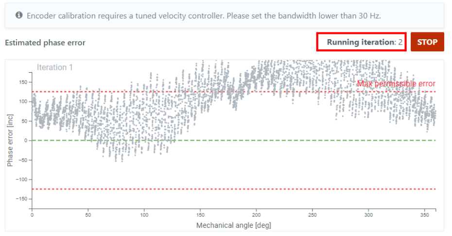
The motor will turn and you will see the progress on the blinking Running iteration n and some updates in the measurement graphs.
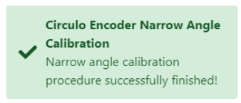
Finishing the calibration successfully will be notified by a pop-up.
If the calibrated encoder is used for the ‘Commutation’ function, the Commutation Offset might change after calibration. There is an automatic Commutation Offset Detection procedure at the end of the Encoder calibration. Note that the current Commutation Offset will be updated and saved to the configuration file. If the automatic Commutation Offset Detection fails, it has to be repeated manually with the production firmware (For details, please refer to Commutation Offset Detection).
On a dual encoder system, the calibration has to be repeated for the second encoder ring (Internal encoder 1) similarly.
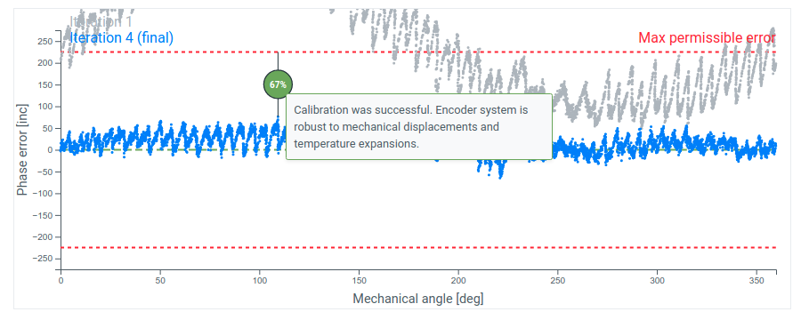
After the calibration procedure is successfully finished, check the estimated phase error plot.
Note the resulting phase reserve - a percentage value in a circle. This value provides the main information about encoder assembly and calibration quality. It should be as big as possible.
Phase reserve after finished calibration:
Phase reserve after finished limited range calibration:
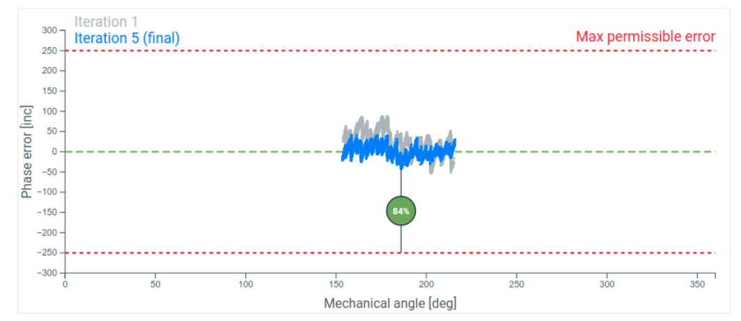
The phase reserve can’t practically be 100% because it’s limited by encoder ring positioning, actual magnetic air gap and ring magnetization quality.
A bigger phase reserve (>50% for Circulo 9 and >60% for Circulo 7) ensures proper operation of the encoder and results in more robust behavior of the encoder system: small mechanical changes, vibration and temperature expansion are less likely to cause an error.
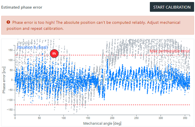
If the phase reserve is 0%, then the encoder system will not provide a reliable absolute position. Check the troubleshooting section.
Note
The calibration procedure might change the absolute position of the encoder up to 11 degrees.
If the system has been homed before calibration or aligned to a reference, repeat the homing or align to your reference once again after calibration. Please install the Production Firmware for this.
After the whole calibration procedure is finished:
Install the latest version of the firmware
Redo offset detection (if the OBLAC Drives version is older than 21.3.0)
Perform Velocity Tuning or Position Tuning (depending on the application)
Attention
The analog calibration procedure must be repeated when the mechanical position of the magnetic ring has changed or the Circulo was re-assembled. This can also occur when mechanical wear has impaired the system performance.
An error will be triggered during startup in the Error Report Object 0x203F when the calibration is required again: BisErBit
You can see a more detailed description of internal errors by using the CHECK ENCODER ERRORS button in the Encoder Calibration tab.
If the Encoder Calibration Procedure has failed during recording, please check the error description and go through the hints in this troubleshooting section. If the calibration is finished, but the resulting phase error exceeds the permissible value, this is usually related to a mechanical issue or magnetic ring damage. It’s possible to identify the cause based on the resulting Estimated phase error graph. There are typically 3 common outcomes:
Note the Nominal air gap for each encoder ring. If the ring is significantly closer, the following pattern will appear in the calibration results: regular high frequency oscillations with a high amplitude.
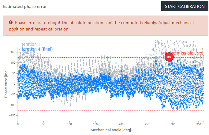
In this case, adjust the encoder ring mounting to ensure the nominal air gap.
Note the Nominal air gap for each encoder ring. If the ring is further away than specified, the following pattern will appear in the calibration results: irregular high oscillations and isolated points (outliers) due to high noise.
The two main reasons for damaged magnetic rings are mechanical scratches and demagnetization. Scratches are typically visible, and minor ones could be tolerated. Their effect on encoder performance can be observed on the phase error curve. The resulting phase reserve should be more than 25%. On the other hand, demagnetization can’t be observed visually or with a gaussmeter. Only the calibration procedure can be used for diagnostics. Note that even a magnetic tip of the screwdriver can disrupt the magnetization pattern.
Attention
Please observe the general handling guidelines for magnetic rings to prevent demagnetization.
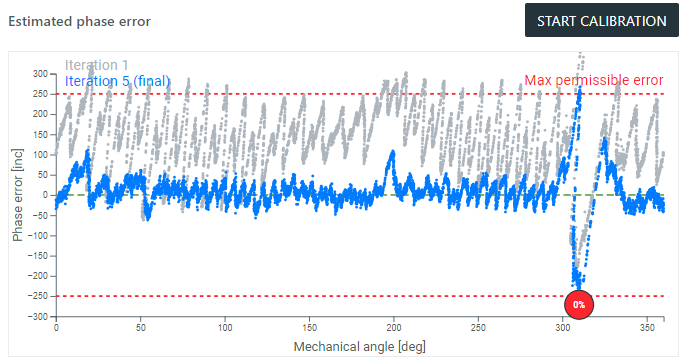
In case of a ring damage, the phase error curve would have a unique error peak.
This set of features allows to:
Check the distance between the chip and the magnetic ring
Detect axial runout of the encoder ring
Read error states directly from the encoder chip
This feature can assist during the prototyping phase of the design. It computes the air gap based on the ring’s magnetic field strength and recommends next action.
Starting from OBLAC Drives v21.3.0 there are 2 supported revisions of magnetic rings:
Ring type |
Characteristic |
SKU number |
|---|---|---|
Revision 1 |
Don’t have any marks on it. |
ACC-002X-01 |
Revision 2 |
Printed text on the outer diameter that includes:
Can have some text on top of the rubber material. |
ACC-002X-02 |
Note
Make sure you are always using the latest version of OBLAC Drives.
Please select the correct ting type in order to get more accurate air gap estimation: Marked or Unmarked.
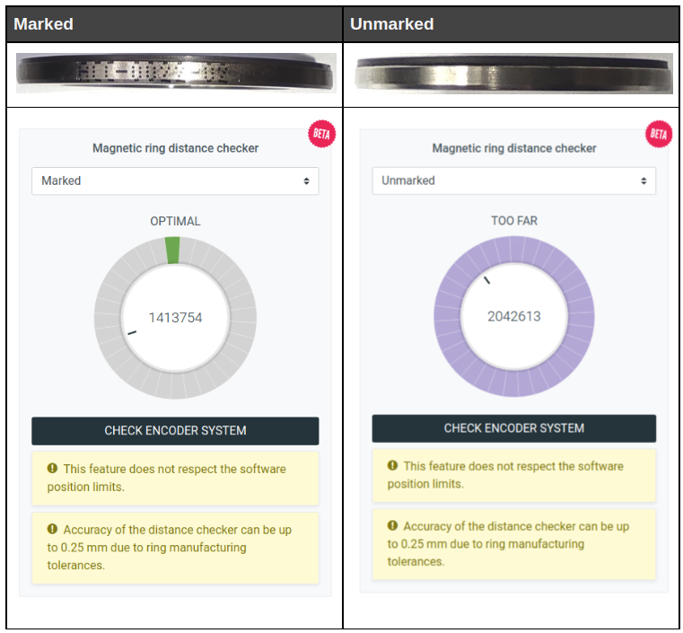
Note
Earlier batches of the Revision 1 encoder rings (Unmarked) had a weaker field, and thus the computed distances might be overestimated. Please use this feature carefully with older encoder rings. It shouldn’t be a primary information source during the ring mounting process, mechanical design should take a priority.
Note
The releases of the OBLAC Drives at version v21.1.0-beta.4 and before display the estimated air gap based on outdated nominal air gap of 0.5 mm for all rings. Please check mechanical documentation and update OBLAC Drives.
Performs a diagnostic test of the encoder system. One rotation of the currently selected encoder will be done in the open-loop field control mode.
The obtained data will be used to compute a distance map over a full revolution. This is helpful to detect distance variations and hence axial runout of the encoder ring or eccentric motion.
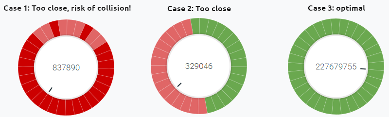
This visualization helps you detect possible problems with the mounting of the encoder ring:
Case 1: Some axial runout detected, the ring is too close. This can lead to a collision with the read head.
Case 2: Axial runout present, check the quality of the encoder ring assembly.
Case 3: No Axial runout detected, this should be the goal.
Attention
The feature currently needs to perform a full revolution and does not respect the software position limits.
This command establishes a direct communication with the encoder chip and the Multiturn counter (if configured). Error registers are read and displayed:
(Name), Description, Remedy |
Detailed description |
|---|---|
(STUP) Encoder startup error. Can appear during Multiturn configuration. Power cycle the drive. |
Encoder initialization error. The typical reason is: not saved Multiturn Counter configuration. Connect the multiturn battery, check the battery voltage, configure the multiturn bits in OBLAC Drives, configure internal encoder and Save To Device. Power cycle the drive. If the error is always present, contact support. |
(AN_MAX) Magnetic field strength is too high. Check mechanical assembly and external fields. |
The inner track of the encoder chip detects too strong a field. Typically, it can’t be generated by the magnetic ring itself at normal conditions. Please check the influence of external fields, especially brakes. |
(AN_MIN) Magnetic field strength is too low for encoder operation. Check positioning of the encoder ring. |
The encoder magnetic ring is too far from the encoder chip or isn’t detected. Check the mechanical assembly. In some rare cases can be provoked by demagnetized ring or field strength drop due to high temperatures. |
(AM_MAX) Magnetic field strength is too high. Check mechanical assembly and external fields. |
The outer track of the encoder chip detects too strong a field. Typically, it can’t be generated by the magnetic ring itself at normal conditions. Please check the influence of external fields, especially brakes. |
(AM_MIN) Magnetic field strength is too low for encoder operation. Check positioning of the encoder ring. |
The encoder magnetic ring is too far from the encoder chip or isn’t detected. Check the mechanical assembly. In some rare cases can be provoked by demagnetized ring or field strength drop due to high temperatures. |
(FRQ_CNV) Encoder maximum speed was exceeded. |
Encoder maximum speed was exceeded. Circulo 7 - 12000 RPM or Circulo 9 - 6000 RPM |
(FRQ_ABZ) Encoder maximum speed was exceeded. |
Encoder maximum speed was exceeded. Circulo 7 - 12000 RPM or Circulo 9 - 6000 RPM |
(NON_CTR) Internal Encoder calibration parameters are outdated or non-existing. Please calibrate the internal encoder. |
The absolute position value can’t be computed reliably at the current position. This can be caused by: encoder wasn’t calibrated, change in encoder mechanics, severe thermal expansion or magnetic target damage. Run diagnostics and repeat the calibration procedure. If this error prevents you from performing calibration - disable it or contact support. |
(MT_CTR) Multiturn Counter synchronization error. Check MT configuration, connect a battery. Power cycle the drive. |
Can happen because of not saved Multiturn Counter configuration. Connect the multiturn battery, check the battery voltage, configure the multiturn bits in OBLAC Drives, configure internal encoder and Save To Device. If the error is still present, please contact support. |
(MT_ERR) Multiturn Counter communication error. Check MT configuration, connect a battery. Power cycle the drive. |
The Multiturn counter is in error state. Connect the multiturn battery, check the battery voltage, configure the multiturn bits in OBLAC Drives, configure internal encoder and Save To Device. Power cycle the drive. If the error is still present, please contact support. |
(EPR_ERR) Encoder EEPROM memory communication error |
Communication with the EEPROM memory of the chip is distorted. Power Cycle the drive. If this can’t be reset, there might be a hardware problem. Please contact support. |
