- Hardware Manuals
- Commissioning and Tuning Guide
- Software Reference
- Resources
Controlling a motor with Field Oriented Control requires precise measurement of the motor’s electrical angle. With phase order and commutation angle offset detection (hereinafter referred to as “Offset Detection”), the relationship between the motor electrical angle and the motor mechanical angle (position sensor feedback) is identified, afterwards the motor position sensor feedback is used to determine the motor’s electrical angle for motion control.
Note
This feature is needed for every motor control setup. The application will not work properly before the Offset Detection routine is successfully executed.
If an incremental encoder without index is used for commutation, the offset detection has to be done on every power on. Otherwise, the routine only needs to be done once during the first commissioning and after mechanical changes of the motor or of the commutation encoder.
The Offset Detection routines identify two parameters for the relationship between the motor electrical angle (rotor magnetic field angle) and the motor position sensor feedback:
The motor phase configuration (NORMAL or INVERTED) (0x2003:5)
Normally, both rotor angle and sensor angle should increase/decrease at the same time. This situation is called “NORMAL motor phase configuration” and is shown in Fig. 1.
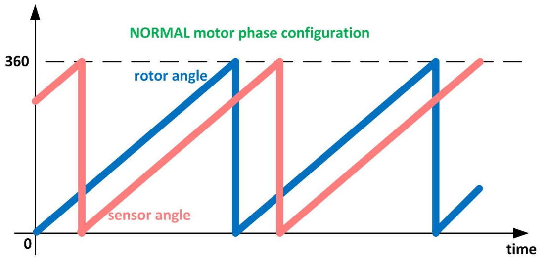
Fig. 1: Normal motor phase configuration (sensor angle and rotor angle are both increasing/decreasing simultaneously)
However, sometimes the angle of position sensor is not increasing in the same direction of rotor angle. This can happen if the position sensor is mechanically flipped, or if two of the stator phases are flipped. Figure 2 shows such a situation where the rotor angle and the position angle are not increasing/decreasing in the same direction. This situation is called Inverted motor phase configuration.
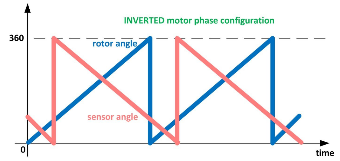
Fig. 2: Rotor angle and position sensor angle are not increasing/decreasing in the same direction (Inverted motor phases)
The commutation angle offset (0x2001:1)
In most cases, the provided sensor angle contains a shift respect rotor angle. Figure 3 shows such a case where the provided sensor angle has an offset respect rotor angle:
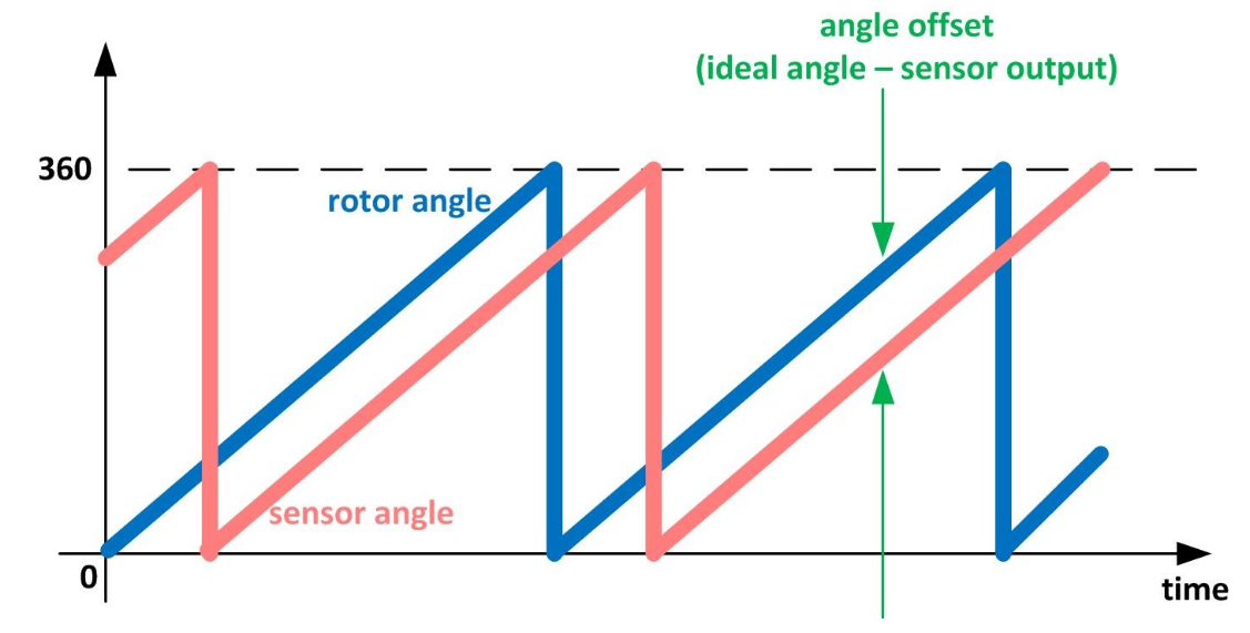
Fig. 3: In most of the cases, the provided sensor angle has a commutation angle offset
Offset Detection is carried out in the Diagnostics Opmode using OS-Commands.
Note
When quick stop is commanded during Offset detection, the procedure is aborted and the drive is disabled.
The active load of the system should be lower than motor rated torque
The position feedback sensor on the motor side should be configured properly and provide proper feedback of the motor position
The motor should be configured correctly
The mechanical system should not block the motor
The brake should be configured correctly and work properly during the routine so that it doesn’t block the system
The power supply used should be able to provide the voltage / current required by the routine
Note
If the requirements are not met, the Offset Detection routine fails and the detection result can be wrong, leading to further failures.
Note
Large single side loads during the routine (such as the gravitational load) can lead to lower detection accuracy with Offset Detection method 0 and 1.
Note
The precision of the commutation angle offset detection depends on the resolution of the encoder that is used. For example, if HALL sensors with a resolution equal to 60 degrees are used, the precision of commutation angle offset detection is expected to be 60 degrees as well.
Three different methods for finding the “commutation angle offset” are implemented. The method can be selected manually (in subitem 0x2009:3). The optimal method is determined by the setup and the use case.
Method 0 is the option used by default. This algorithm has the following characteristics:
It needs no tuning
It is able to hold the load
The offset can be precisely measured
It will rotate the rotor up to 100% of a pole-pair range
Attention
This method is still in prototype phase and can be tested at the user’s own risk.
This algorithm has the following characteristics:
It needs previous tuning of the controller with a dedicated set of gains: the phasing controller whose parameters are located in object 0x2009
The offset can be found with a limited movement range. With a well tuned PID controller the movement is typically less than 5 degrees
The offset can be measured very precisely
Attention
This method is still in prototype phase and can be tested at the user’s own risk.
This algorithm has the following characteristics:
It needs no movement (no rotation)
If a brake is available, the brake should be engaged while offset detection method 2 is in progress.
Attention
If no brake is available and mechanical load is relatively small (compared to rated motor torque), then offset detection method 2 can lead to rotor movement
It is not able to hold the load. As a result, when a brake is present, the brake will remain engaged during the procedure of offset detection method 2.
It can take up to 250 milliseconds.
The precision of method 2 is not as high as methods 0 or 1.
Note
This method can cause audible noise when it’s executed.
The optimal method depends on the use-case. The following tables shows the advantages and disadvantages of each method.
| Method # | Tuning necessary? | Able to hold a load? | Precision of measurement | Rotation required | Notes |
|---|---|---|---|---|---|
| 0 | No | Yes | Good | up to 1 pole-pair range | |
| 1 | Yes | Yes | Good | Depends on quality of tuning. Typically less than 20 electrical degrees. | |
| 2 | No | No* | Less good | None |
|
* This procedure is usually carried out with applied brakes.
Method 0/1 should be used
Method 0 gives perfect precision without any previous tuning.
If the final system has coupled joints or heavy or single side loads it might be required to perform Offset detection before assembly for optimal performance.
If the movement of up to one pole pair is not acceptable method 1 can be selected, where the movement can be much less. The PID controller used for method 1 needs to be tuned carefully.
Note
Try moving the arm to a position in which gravity has no or little impact, for optimal performance of the detection. For example the center of gravity should be right above or right below the axis of motion.
When no movement is allowed during commissioning, method 2 can be used. This may happen when the setup is already in the application. Note that the method has less detection accuracy, thus the commutation efficiency can be less. In this case, it’s recommended to redo Offset Detection when the setup is allowed to move.
If an ABI encoder is used for commutation, a routine called “finding index” is usually required when enabling the drive (the first time after booting the system), which will rotate the motor to find the index of the sensor. With commutation method 2, the drive can find an internal temporary offset and use this offset until the index is detected. Once the index is detected, it replaces the temporary offset by its corresponding value in the object dictionary. In practice, Offset Detection can be carried out with method 0/1 during commissioning, the result can be saved and method 2 can be executed. This way, no movement is required when enabling the setup, and the torque control performance of the setup is still promised.
Offset detection is usually carried out in the setup section of your motor in OBLAC Drives. The commutation offset detection method is chosen with subitem 0x2009:3. The default method is 1.
Attention
When the existing Offset Detection results become invalid, try locating the cause and fix the system-level failure instead of running Offset Detection again. Else further failures can happen.
The procedure can also be triggered manually for production use:
Steps to activate the “commutation angle offset chain”:
In object 0x6060: (Modes of operation) set the value to -2 (Diagnostics mode)
In subitem 0x2009:3 select the offset detection method (values: 0, 1 or 2)
In object 0x6040 Controlword switch the CiA402 status to “Operation_Enabled”
The procedure will start automatically.
Trigger the following OS commands to carry out offset detection:
Command 6: Open phase detection
Command 8: Phase resistance measurement
Command 9: Phase inductance measurement
Command 7: Pole pair detection
Command 4: Motor phase order detection
Command 5: Commutation offset measurement
Autophasing during initial configuration of a drive with absolute encoder:
The following steps are mandatory:
Command 6: Open phase detection
Command 7: Pole pair detection (on new type of motor)
Command 4: Motor phase order detection
Command 5: Commutation offset measurement
Autophasing after power on with incremental encoder:
The following steps are mandatory:
Command 4: Motor phase order detection
Command 5: Commutation offset measurement
Note
Motor phase order detection is mandatory in order not to damage the system.
The gains for PID tuning can be found in object 0x2009 :
Subitem 0x2009:4 defines K p for method 1.
Subitem 0x2009:5 defines K i for method 1.
Subitem 0x2009:6 defines K d for method 1.
Note
As a rule of thumb, the following approach can be applied:
Start values of the gains:
K p = 1
K i = 1
K d = 0
Increasing and decreasing K p and K i will have the same effect as increasing them in a simple PID position controller.
If needed, the increase in K d should be done in very small steps (such as changing from 0 to 0.001), this will reduce the oscillations of the load.
0x2003 Motor Specific Settings
Details for your motor specification.
Subitem 0x2009:1 shows the state of the commutation offset.
Subitem 0x2009:2 defines the amount of torque that is applied during the offset detection process.
Subitem 0x2009:3 determines the method to be used for offset detection.
Subitem 0x2009:4 defines K p for method 1.
Subitem 0x2009:5 defines K i for method 1.
Subitem 0x2009:6 defines K d for method 1.
Determines what percent of rated motor currents should be injected into the motor phases during the offset detection procedure.
The rated torque of your Motor according to the data sheet.
Selects the mode of operation.
Sets the status of the drive
