- Hardware Manuals
- Commissioning and Tuning Guide
- Software Reference
- Resources
In this document, the steps of tuning gain scheduling position controller are explained. The structure of gain scheduling controller is the same as for a basic cascaded controller shown in Fig. 1.
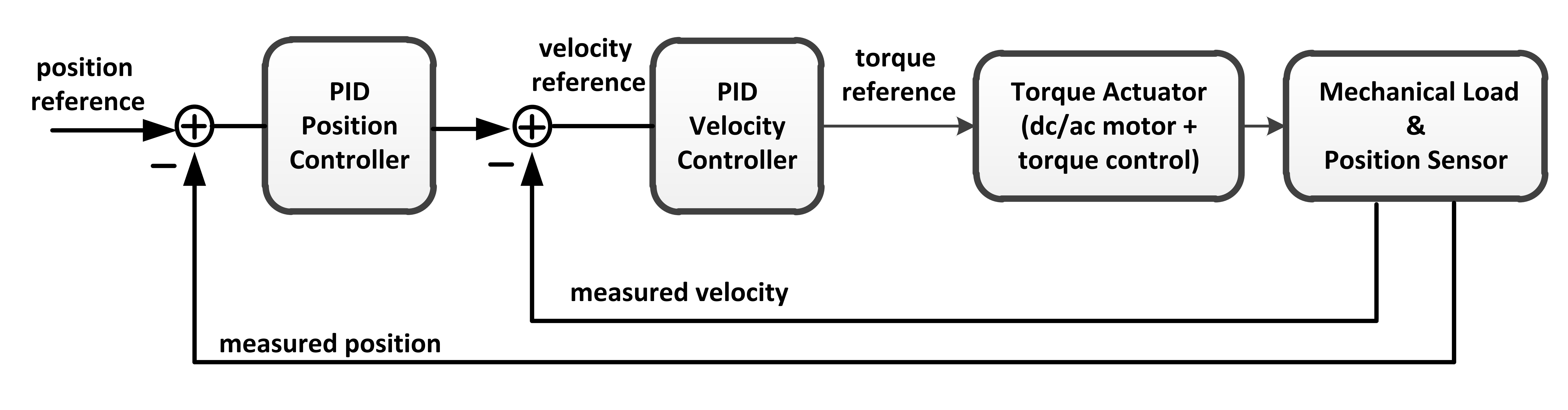
Fig. 1: Cascaded position control structure
Gain scheduling controller changes gains based on measured velocity of the axis. Basically it uses two sets of gains, one set is used when the system moves with low velocity and the other set is used for high velocities. User sets two parameters for low and high velocity area, i.e. low velocities are bounded with upper limit (low velocity limit) and high velocities are bounded with lower limit (high velocity limit). Between limits gains are changed linearly. By seting the velocity limits user can control how often the gains will change, i.e. user can adjust behaviour of controller depending on the dynamics of the system.
Measuring units of gains of position controller are:
kP [rpm/ticks]
kI [rpm/ticks*s]
kD [rpm*s/ticks]
Measuring units of gains of velocity controller are:
kP [mNm/rpm]
kI [mNm/rpm*s]
kD [mNm*s/rpm]
Tuning of the gain scheduling controller is the same as for cascaded controller but it has to be done two times. One tuning should be done for the low velocity dynamics and the other one for high velocity dynamics. It is expected that the gains for lower velocities (axis is close to reference position) will be higher (controller reacts faster on overshoot and steady state error) then the gains for higher velocities (system is far away from the reference position). Usually the schedling of gains depending on axis velocity looks like on the picture shown in Fig. 2.
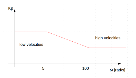
Fig. 2: Scheduling of gains depending on velocity
Integral limit of the velocity controller should be set to the maximum torque of your torque actuator (in mNm) and integral limit of the position controller should be set to the maximum velocity of your system (in rpm).
Tuning steps decribed for cascaded controller should be applied for tuning the gain scheduling controller. First the controller should be tuned for high velocities and then for low ones. In the following section, the explained tuning concept is divided in separate systematic steps.
Set the reference step signal to a higher value, which will cause the axis to move with high velocity. Set the PID constants of both controllers equal to 0. By default, the integral limit of the velocity controller should be set to motor maximum torque in [mNm], and the integral limit of position controller should be set to motor maximum velocity in [rpm].
Important
from this step forth, the step response of position controller should always be evaluated.
In this step, the kP constant of the velocity controller should be tuned. Increase the kP of both position and velocity controllers with a ratio of 10 (kP_velocity = 10 * kP_position). Once the real position starts to follow the reference position, stop increasing the kP_position and only focus on increasing the kP_velocity. Increase (sharpen) the velocity controller as much as possible. As a rule of thumb, increase kP_velocity until you get close to the instability margin (at this margin, you will feel a vibration effect and some acoustic noise which is because of controller sharpness). Now, you can reduce kP_velocity to 90% of its value to increase the stability margin, and remove vibration noise.
Now that the velocity controller is tuned, it is time to tune the parameters of the PID position controller. Start with kP_position, and increase it until you again get close to the instability margin, and then reduce kP_position to its 90%. So far, the proportional parts of both inner velocity loop and outer position loop are tuned.
In this step, increase kI to eliminate the steady state error. As a suggestion start with kI equal to 0.01, and in each step, increase it with a factor of 2. Increase kI step by step until the following two conditions are met at the same time:
the overshoot is in its acceptable range
the steady-state error is eliminated in a short enough period of time
Repeat steps 1 - 4 for a small step reference signal (couple of thousands of ticks).
At this stage gains of the controller are determined. Beside gains user needs to determine the limit for low and high velocity dynamics. Recommendation is to observe the value of velocity during the tuning process. This should give a good basis for selection of those limits.
