- Hardware Manuals
- Commissioning and Tuning Guide
- Software Reference
- Resources
This feature allows to supervise the work of the control loops. This includes monitoring the internal variables and basic analysis of the control loop performance. Some monitoring functions and data objects are available only in specific control modes.
The main supervision functions are:
Following error - Basic function that needs to be calculated on the master
Following error window - Advanced feature that raises a flag in the Statusword
Target reached function - Raises a flag in the Statusword
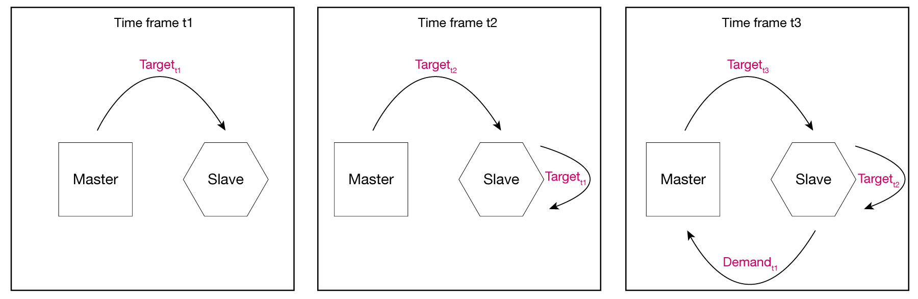
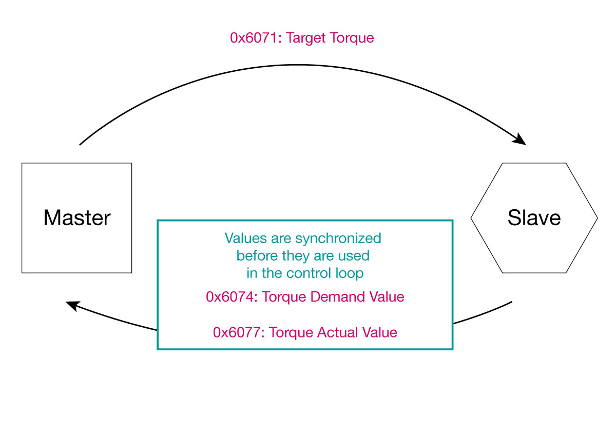
Two communication cycles after the master sends a target value to the slave (position/velocity/torque), the slave sends back two values: the Demand Value, indicating the value that was received by the slave and the Actual value as read from the sensors. These values are synchronized and sampled from inside the control loop.
Name and designation of these objects differ, depending on the chosen mode of operation:
Note
The easiest way to measure the performance of a control loop is to calculate a following error:
Following error = Target value - Actual value
If the master-generated value is used as a target value, it is not synchronized with the actual measured value. The typical delay can be up to 3 communication cycles. Thus, the computed error will contain an extra error due to communication delay.
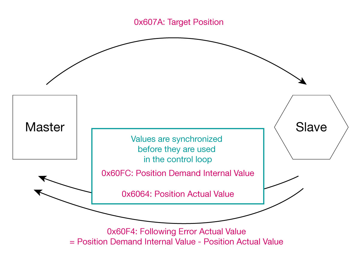
To circumvent this issue, ‘Demanded value’ objects should be used. These values a sampled synchronously with the actual measured value and should be used to correctly compute the following error.
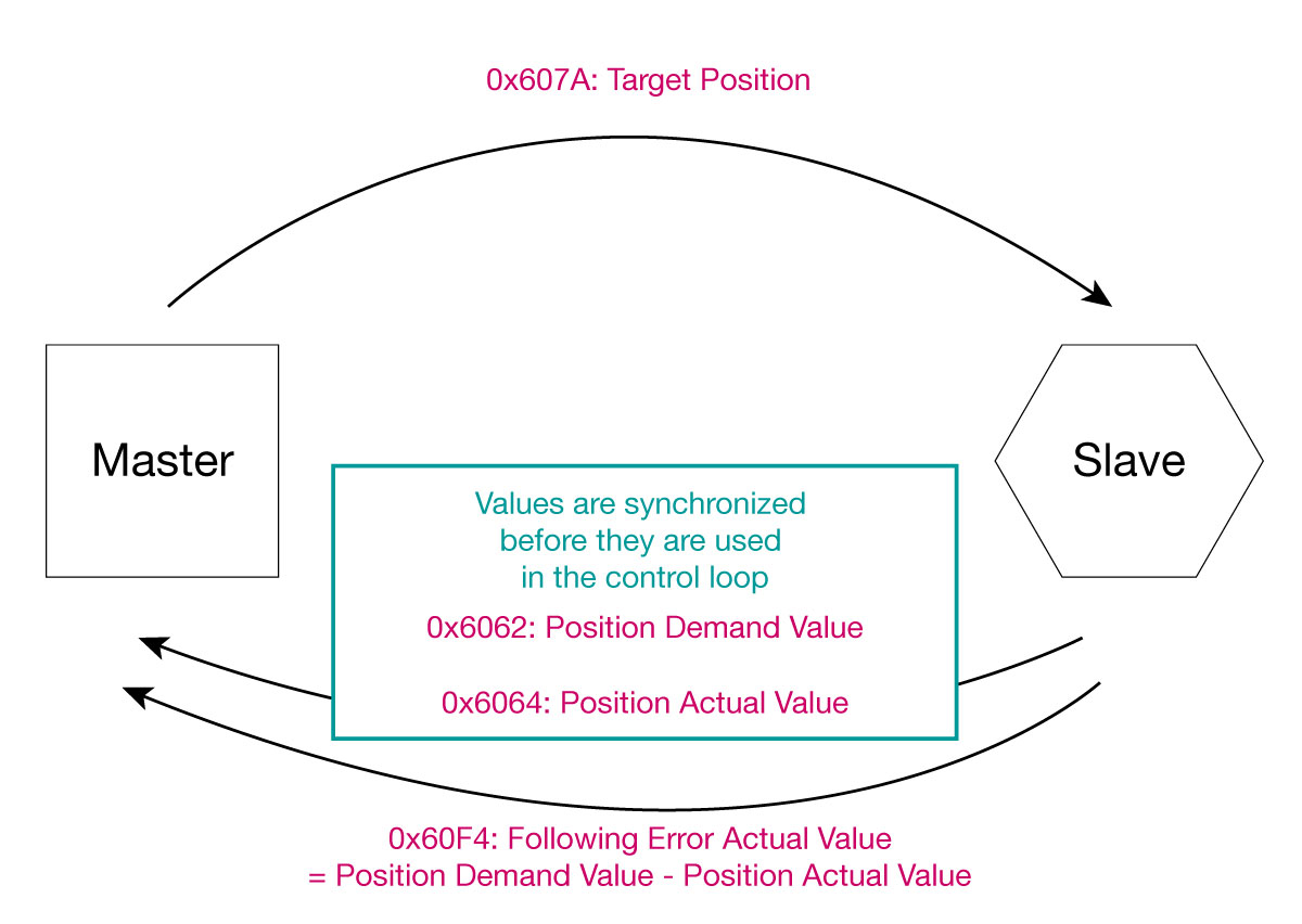
Example: Velocity following error = Velocity demanded value - Velocity actual value
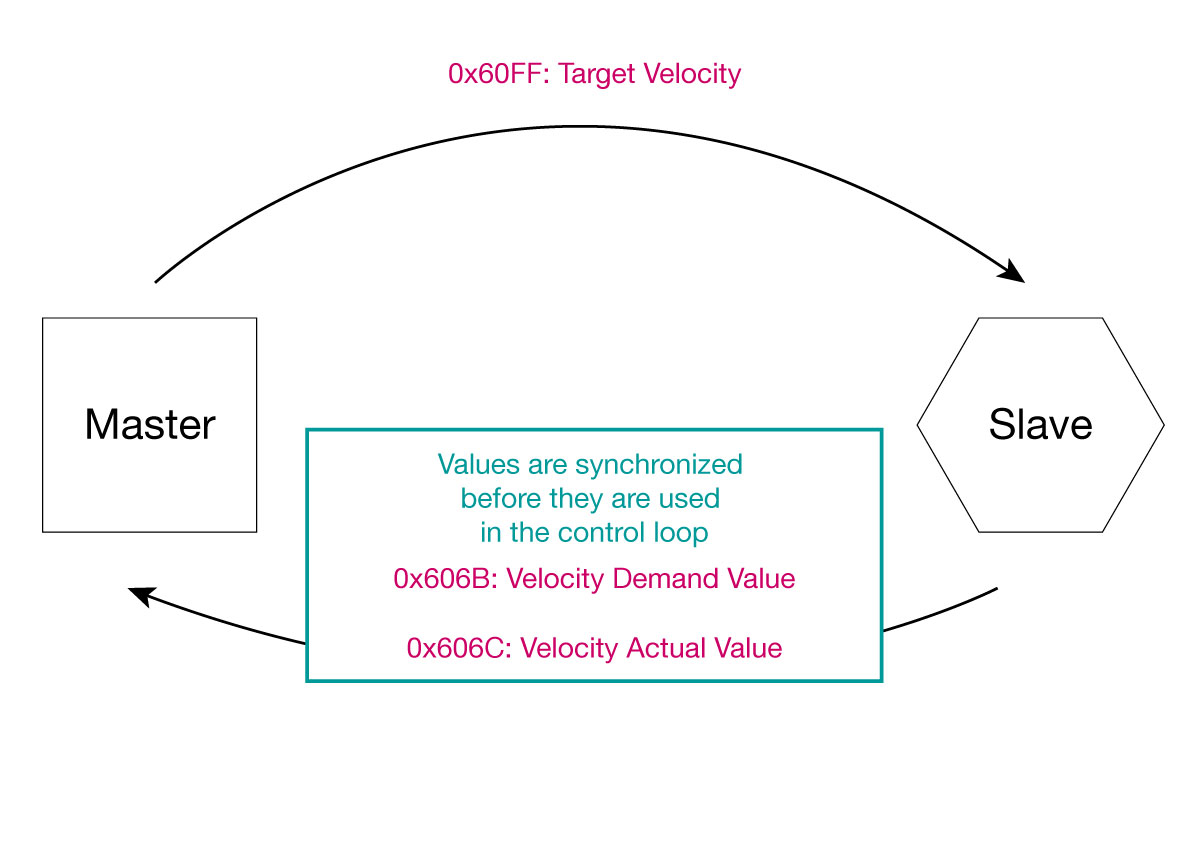
Alternatively, the object Following error actual value (0x60F4) can be used to monitor the position control loop.This object is also used for the Following Error Window feature.
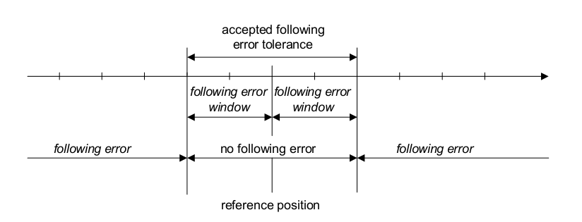
If the actual value is outside of the configured window for a configured period of time, the user is informed that the following error is bigger than the configured value.
This information is reflected by bit 10 of the statusword.
Use case: Predictive maintenancing (monitor system wear)
In case the following error grows bigger in time, check if mechanical wear is the reason.
Note
The Following error window feature can only be used in a position control mode (operational modes CSP and PP)
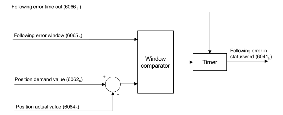
Following error window 0x6065 [inc]: Use this object to indicate half of the configured range of tolerated position values symmetrically to the position demand value. If the position actual value is out of the following error window, a following error occurs. If the value of the following error window is FFFF FFFF h , the following control is switched off (default).
Following error timeout 0x6066 [ms]: Use this object to indicate the minimum time that the actual position must be out of following error window so that the bit 13 of the statusword is raised to 1, indicating that a Following error has occurred.
Bit 13 of the Statusword indicates that the following error is outside the allowed window:
0: value within error tolerance
1: value exceeds error tolerance
Following error actual value 0x60F4 [inc]: Provides the actual value of the following error.
This feature can be used to inform the user if the requested target was reached (for example if the target position was set in the Profile mode). A specified target (position, velocity or torque) can be defined with a margin at each side.
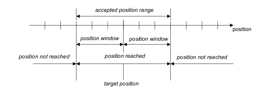
If the actual value is inside of the accepted position range for a configured period of time, the user is informed that the target position has been reached.
This information is reflected by bit 10 of the statusword.
Use case: Pick and place operation
In case the real position where the good is to be picked up or placed has more margin than the precision of the motion control system, using a wider position window allows a faster operation.
Note
The accepted position range is calculated as two times the position window.
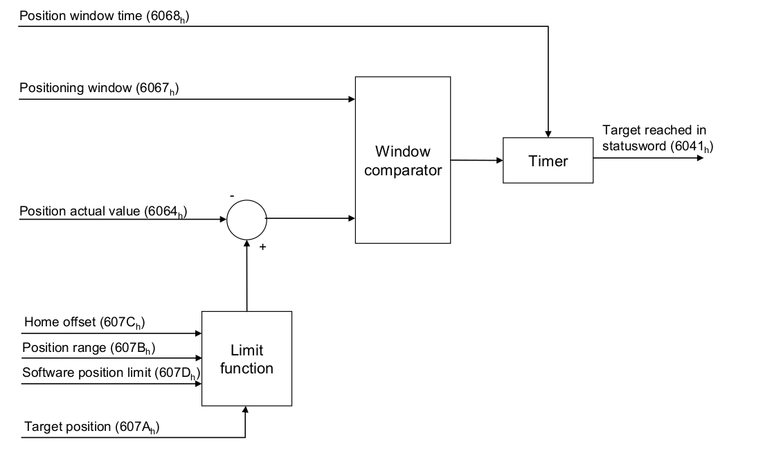
Enter the position window value in object 0x6067 Position window (unit is given in increments of the position encoder). The value 0xFFFFFFFF switches the feature off (default).
In object 0x6068 Position window time you can configure the time required for the position sensor to remain within the position window before it’s considered to be inside the window. The unit is given in ms.
Note
The accepted velocity range is calculated as two times the velocity window.
Enter the velocity window value in object 0x606D Velocity window (unit is given in rpm) The value 0xFFFF switches the feature off (default).
In object 0x606E Velocity window time you can configure the time required for the value to remain within the velocity window before it’s considered to be inside the window. The unit is given in ms.
Note
The accepted torque range is calculated as two times the torque window.
Enter the torque window value in object 0x2014 Torque window subitem 1.
In subitem 2 you can configure the time required for the torque value to remain within the torque window before it’s considered to be inside the window. The unit is given in ms.
Bit 10 of the Statusword indicates that the position is within the allowed window:
0: value outside accepted position range (position not reached)
1: position reached
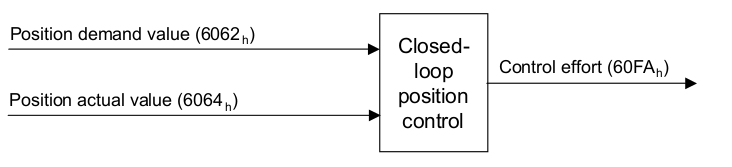
To examine the inputs and outputs of a given controller, the following objects can be used:
Position demand value 0x6062: Provides the value of the position sent to the position controller after position limits are checked. (See 0x607D Software position limit.) The units are in increments of the position encoder.
Position demand internal value 0x60fc: Provides the output of the trajectory generator in profile position mode. The units are in increments of the position encoder.
Position value 0x6064: Provides the actual value of the position encoder. The units are in increments of the position encoder.
Velocity demand value 0x606b: Provides the output value of the trajectory generator in velocity control, and the output of the position controller when using the cascaded controller. The units are user-defined (RPM by default; see 0x60a9 SI unit velocity to change it).
Velocity value 0x606c: Provides the actual velocity value derived either from the velocity sensor or the position sensor. The units are user-defined (default is RPM; see 0x60a9 SI unit velocity to change it).
Torque demand 0x6074: Provides the output value of the torque trajectory generator. The units are per thousand of rated torque.
Torque value 0x6077: Provides the actual value of the torque, and is computed based on the currents measured in the motor. The units are per thousand of rated torque.
The control effort (object 0x60FA) is the output of the controller for the selected mode.
It provides a measure of the control effort (the output of the control loop).
The units are per thousand of rated torque.
Half of the configured range of tolerated position values.
0x60F4: Following error actual value
Provides the actual value of the following error.
0x6066 Following error timeout
Minimum time that the actual position must be out of the window so that a following error is triggered.
Half of the accepted position range.
Time required for the position sensor to remain within the position window.
Half of the accepted velocity range.
Time required for the value to remain within the velocity window
Indicates the accepted torque values and time.
Value of the position sent to the position controller after position limits are checked.
0x60FC Position demand internal value
Provides the output of the trajectory generator in profile position mode.
Provides the actual value of the position encoder.
Value of the trajectory generator in velocity control / output of the position controller in cascaded control.
Provides the actual velocity value derived either from the velocity sensor or the position sensor.
Provides the output value of the torque trajectory generator.
Provides the actual value of the torque
Output of the controller for the selected mode