- Hardware Manuals
- Commissioning and Tuning Guide
- Software Reference
- Resources
Since the mounting situation is highly dependent on each individual design, an example of a hollow shaft robotic actuator is presented that features the most important aspects.
The example project can be downloaded as a STEP file.
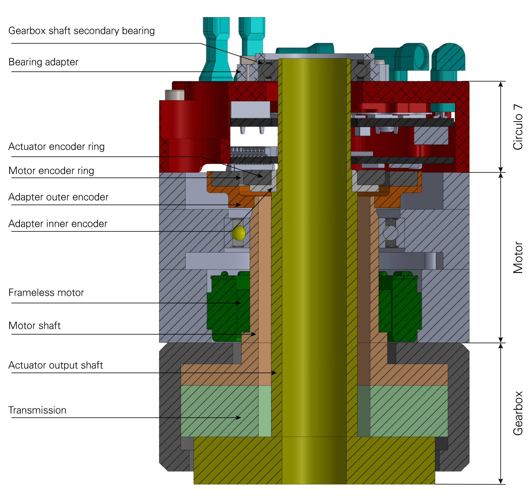
Circulo 7 mechanical integration example
It comprises the following components as shown in the graphic.
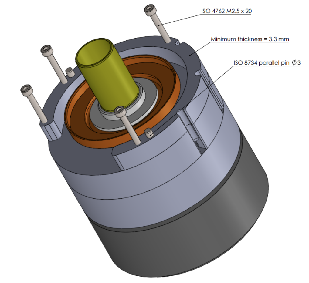
Circulo should be mounted to an even metal surface using 4 ISO 4762 M2.5 x 20 screws, tightened to 1 Nm and using a screw lock (tested with Loctite 243). If the Circulo internal encoder is used, it is mandatory to use two 3 mm ISO 8734 dowel pins for aligning the Circulo internal encoder read heads with the actuator. Circulo is designed to induce excess heat into the actuator body, so it is recommended that the mounting surface covers all the heatsink’s lower surface for optimal thermal performance.
The heat conducting surface should be sufficiently dimensioned and made of a suitable material, such as aluminum.
Ensure that the servo drive is screwed properly to the heat conducting surface to facilitate the heat transfer.
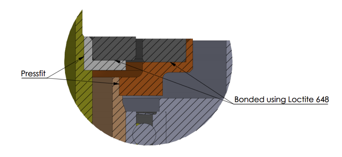
If Circulo’s internal encoders are used, it is important that the recommended tolerances are respected. In this example, the inner encoder is used to measure the actuator position (reducer output) while the outer encoder measures the motor position. The magnetic rings are bonded to the aluminum adapters using an adhesive for gluing the hub to the shaft (tested with Loctite 648) and a H7/g6 fit for the inner and G6/h7 for the outer encoder disc. These aluminum adapters are connected to the appropriate shaft by a press-fit connection. It is important that these parts are machined and assembled accurately, as all mechanical imperfections influence the encoder’s performance.
More details about mounting encoder rings can be found in this section.
When the hollow shaft is connected to the actuator output shaft it is normally quite long and only supported by a bearing on the side of the gear system. Therefore, it is important to support the shaft on the opposite side of the actuator to prevent the shaft from an eccentric motion. If it is not supported properly this might result in poor performance or even failure of the corresponding position encoder.
Note
The bearing adapter must be designed individually according to each application.
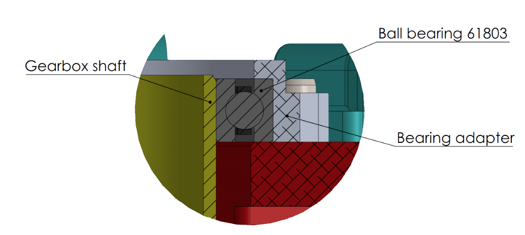
The top side of Circulo provides multiple threaded M2 holes and two holes for 3 mm dowel pins. In this application example a ball bearing (61803) is fitted to this interface to align the output shaft.
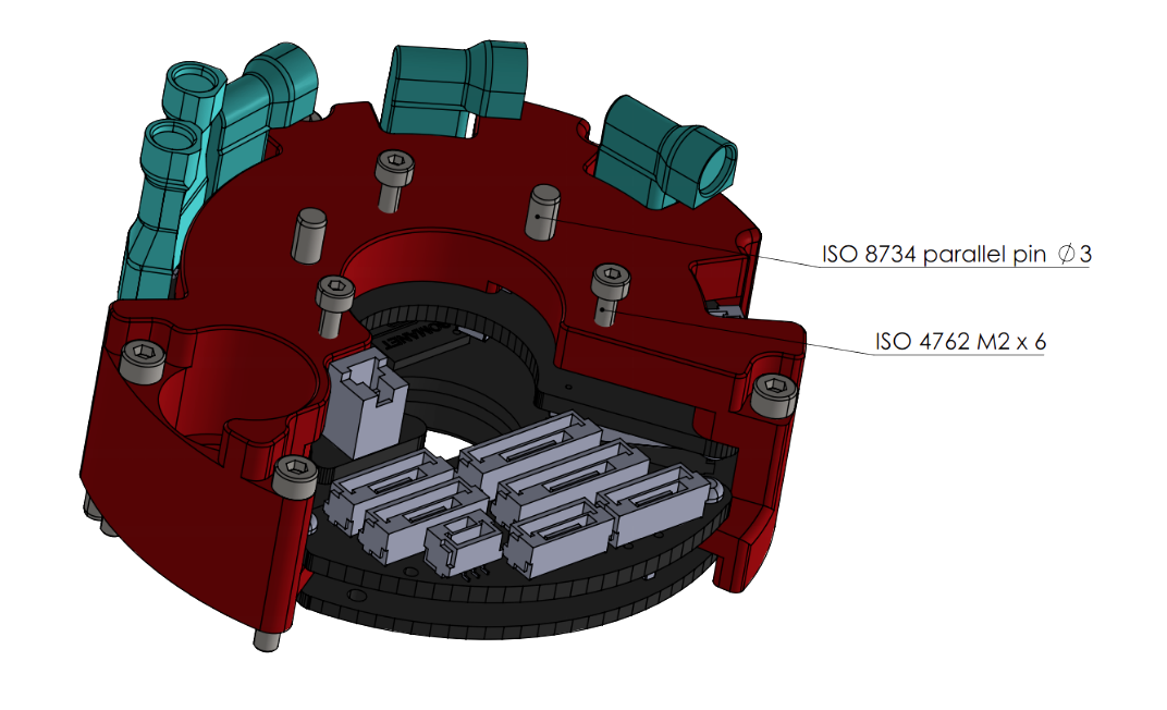
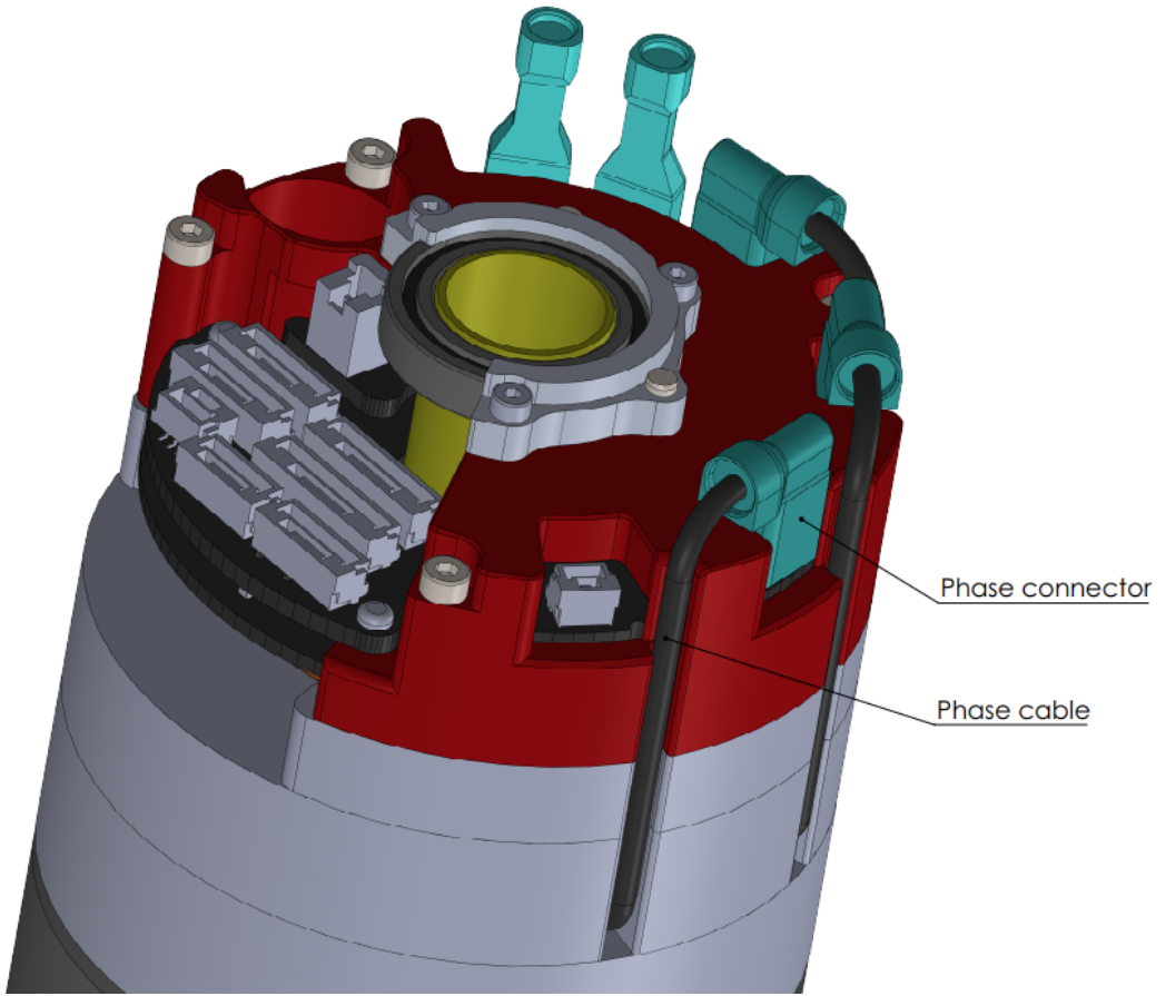
Circulo features cutouts in the heatsink designed for routing the motor phase cables. It is recommended to use these cutouts so that the outer diameter of the actuator is minimized and to shorten the cable lengths to avoid unnecessary cable tangle.