- Hardware Manuals
- Commissioning and Tuning Guide
- Software Reference
- Resources
In any application with servo drives, the power consumption and regenerated power must be taken into account. An unstable power line causes harmful harmonics and could damage the system. In most applications, there is more than one drive which requires an accurate sizing of the DC bus. A system with minimum failure rates and little power consumption can be realized by properly sizing the bus capacitors, braking choppers, power supplies, cabling, earthing and using the right connectors. It’s recommended to use a protected extra-low voltage supply (PELV) instead of a safety extra-low voltage supply (SELV). If a SELV is used, it’s possible that the isolation from the earth can be violated through the servo drive (e.g. through heatsink or mechanical mountings) and the supply becomes PELV.
The nominal supply voltage is the voltage that we recommend to set on your power supply (or use a battery that is within this range).
Maximum voltage ratings divide into continuous maximum and peak maximum ratings. The maximum continuous voltage is a voltage that can also be set on your power supply / battery, if all voltage-related effects are well under control. In particular, it must be made sure that neither recuperative braking nor high frequency (typically 32 or 64 kHz) voltage ripple lead to exceeding the allowable maximum continuous voltage value permanently or cyclically. The peak maximum voltage should never be reached in regular operation. It can only be used as a reserve for rare events, no longer than 1 second and not repeatedly.
The minimum voltage is for configuration purposes only.
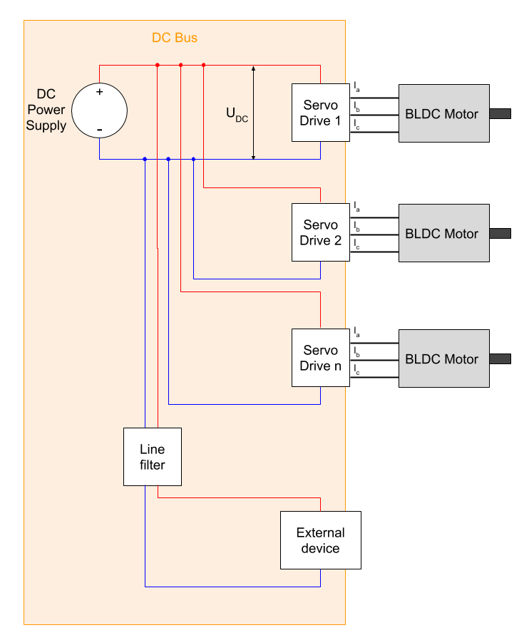
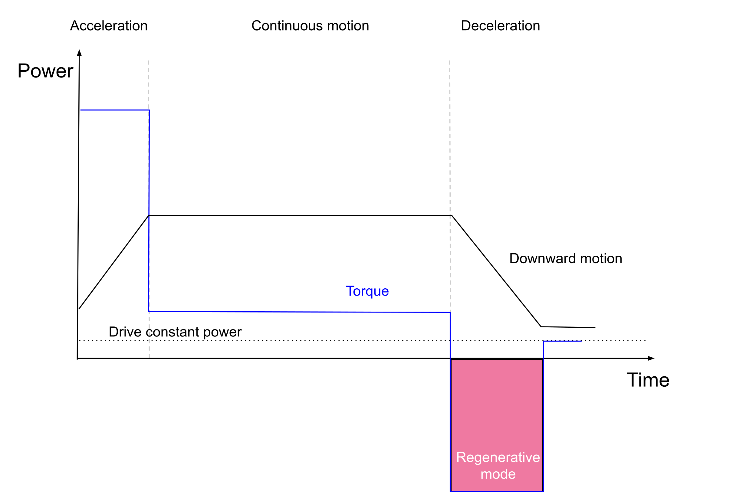
Electrical motors are reversible machines that can act as a motor or generator. When a voltage is applied to the motor, a torque is generated that causes acceleration. But the motor will generate power during deceleration. Regenerative energy can be a serious issue when high inertia, low friction axes undergo fast deceleration. If no counter-measures (particularly adding a braking chopper to the circuit) are taken, the voltage in the DC bus will rise beyond the overvoltage threshold of the servo drives which will cause the drives to switch off and thus the system will become uncontrollable. The problem will be exceeded in multi-axis applications with heavy loads that are affected by gravity. For details, please see section Regenerative energy
The bus capacitance consists of all capacitances on a DC link:
DC bus capacitance = power supply capacitance + drives capacitances + other capacitances
An insufficient capacitance will reflect ripples on the DC link that can provide unwanted harmonics which result in more faults.
In addition to coping with ripples on the DC bus, the capacitor can also absorb part of the regenerated energy resulting from deceleration (see Regenerative energy). But using capacitors will not be enough for large amounts of energy - the excessive energy needs to be dissipated with braking resistors.
The amount of energy (in joules) stored by a capacitor is determined by the capacitance (C) and voltage (V) and is given by:

v 1 is the nominal voltage.
v 2 is the maximum voltage level that is limited by the braking chopper or a braking resistor.
C is the total capacitance of DC BUS (Power supply capacitor + External capacitor + Drive capacitor).
Example
v 1 = 48 V
v 2 (protection voltage level) = 55 V
C = 3 mF
E cap calculates to:
 , which means the capacitor can absorb 1.08 J of regenerated energy. Increasing the capacitance is costly and requires space. For estimating the minimum DC link capacitance consider 0.5 µF for 1 W drive power. It is recommended to use a 470 µF capacitor for a SOMANET Node 1000. If the power supply capacitance is more than the estimated capacitance, no additional capacitors are required.
For sizing a power supply, the following questions need to be answered:
How much Watt does the system need?
Voltage level and Amperage
Power losses and constant power consumption
Peak power and average power
Will regeneration be a concern?
Power supply capacity
Braking resistor
At what voltage level should the system operate?
Should a battery or a switching power supply be used?
Switching power supplies are the most common power supplies for industrial applications, but some applications require batteries. There are some considerations for selecting a suitable power supply. The power supply should be able to provide the demanded power. For the power calculation, the maximum power of each motor and its duty cycle need to be considered for selecting a proper power supply. In rare cases, regenerative power can be helpful when the system features several servo drives which accelerate and decelerate.
Example: SCARA robot with four axes, each axis utilises a Node 1000.
A 48 V power supply is considered. A 4 kW power supply would be required if all axes need to reach maximum power at the same time. It is not plausible that all the axes require their maximum power at the same time. Considering the robot application, usually two axes can move in a pick and place program at the same time. So in this case a 2 kW power supply could be used. A 20% margin is preferable, so a 2.4 kW power supply is an appropriate power source.
In a single-axis system, the power supply must be able to provide the peak power required by the application while the real consumption depends on the motors and operating point.
The above-mentioned rule of thumb can be exceeded by no more than 50% in extreme cases, however in many practical use cases even less power is sufficient. This is particularly the case if high rpm and high torque are not demanded at the same time, but only separately from each other.
In a multi-axis system with n servo drives, it is typically not required to install n-times the peak power of a single servo drive. This is because in most multi-axis systems, not all axes go to maximum power (maximum torque and maximum speed) at the same time. In robot arms, typically only axes 1 and 2 (SCARA) or axes 2 and 3 (5/6/7 axes robots) are sometimes simultaneously consuming close to full power, so considering the sum of their peak power demands as criteria for the power supply dimensioning is a good starting point.
Power supply current is derived from the power by
P DC = U DC * I DC
SOMANET servo drives are designed for voltages between 12 V and 48 V (60 V Max). Please do not use contactors behind the power supply since the transient-voltage-suppression diodes could get damaged due to the power-up voltage increase (Surge). This is likely to happen when the power-up occurs fast.
This can lead to complete failure of the servo drive.
It is recommended to use a 48 V DC power supply that is common in many industries. A power supply with a significant capacity is required for a servo drive application. Up to 55 V is tolerable for a long time and up to 60 V is acceptable for a time shorter than 1 second. This would allow for regenerative braking of any robot arm, but might be dangerous in systems where gravity provides regenerative power over a longer time, for example in lifting systems or AGVs.
Regenerative currents can occur depending on the commanded trajectory. If the power supply cannot withstand such currents, a braking chopper system must be used additionally.
