- Hardware Manuals
- Commissioning and Tuning Guide
- Software Reference
- Resources
The velocity control modes allow the EtherCAT master to send desired velocities to the SOMANET drive. The drive will make sure these velocity values are reached by the motor (if the motor is physically able to do so).
In this mode, the trajectory generator is located in the control device, not in the servo drive. In a cyclic synchronous manner, it provides a target velocity to the drive device, which performs velocity control and torque control. If desired, the position control loop may be closed over the communication system. Optionally, a velocity offset and a torque offset may be provided by the control system in order to allow a second source for velocity and/or a torque feed forward.
Position sensors are supported and the velocity may be calculated by taking the derivative.
The cyclic synchronous velocity mode covers the following sub-functions:
demand value input;
velocity capture using position sensor;
velocity control function with appropriate input and output signals.
The behavior of the control function is influenced by control parameters such as limit functions, which are externally applicable.
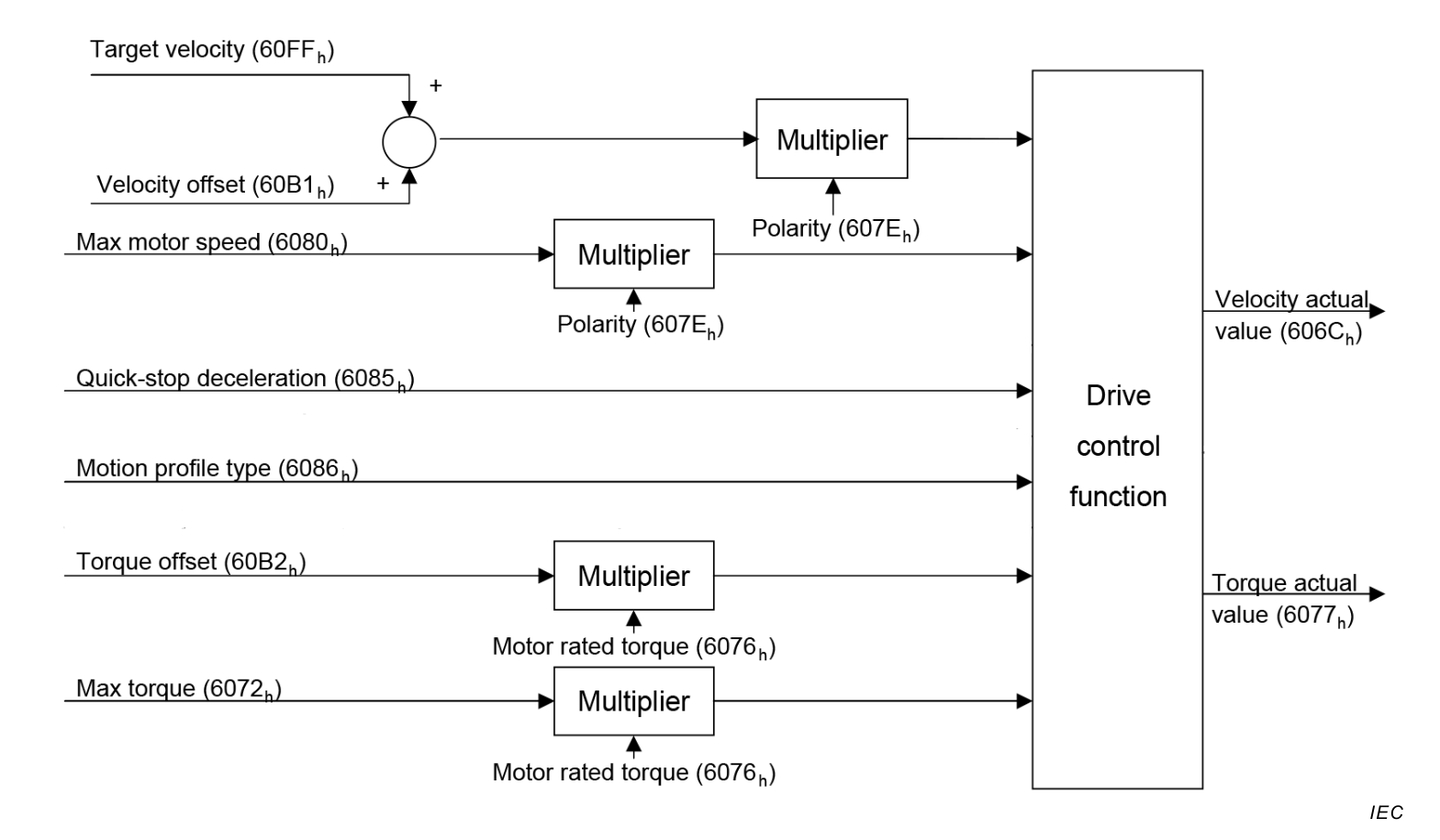
The figure above shows the inputs and outputs of the drive control function. The input (from the control device point of view) are the target velocity and optionally, a velocity offset (to be added to the target velocity) as well as a torque offset. The drive control function in the diagram contains both the velocity controller and the torque controller, where the output of the velocity control loop is used as an input for the torque control loop.
The drive device supports limitation of motor speed and a quick stop function for emergency reasons.
The time period between two updates of the target velocity and/or additive velocity can be interpolated for smooth trajectories.
The velocity actual value is used as mandatory output to the control device. Another output is the torque actual value.
All values are in rpm by default and can be converted to user defined velocity units if needed.
This mode uses some bits of the statusword for mode specific purposes which are indicated in yellow. The figure shows the structure of the statusword. For the general structure and usage, please refer to our Application note on Status- and Controlword.
The mode specific bits of the statusword can be used to monitor the performance of the operation. For further information please refer to the section on Control Supervision.
| 15-13 | 12 | 11 | 10 | 9-8 | 7-0 | |||||
|---|---|---|---|---|---|---|---|---|---|---|
| N/A | Target velocity ignored | Internal limit active | Target reached | N/A | basic | |||||
Internal limit active:
Target reached: The bit is set if the actual velocity stays in the window of target velocity ± velocity window for a duration of Velocity window time.
Target velocity ignored: This bit is set if Target velocity 0x60FF is equal to Velocity demand value 0x606B. It means that the user command is passed directly through as an input of the velocity PID controller.
However, if Target velocity is limited by Max. motor speed, the limited value will be used as an input of the PID controller and the bit will be cleared.
Note
0 = Target velocity ignored1 = Target velocity shall be used as input
Values Kp, Ki and Kd for Torque Controller
Values Kp, Ki, Kd and Controller Integral Limit for Velocity Controller
Use this object to directly select a Target velocity
