- Hardware Manuals
- Commissioning and Tuning Guide
- Software Reference
- Resources
The brake voltage is a square wave signal 16 kHz, 32 kHz or 64 kHz (configurable in subitem 2004:11). A PWM method is used for applying the appropriate voltage to the brake output.
The brake output voltage does not have a negative component. It is connected to an inductor which results in a constant current.
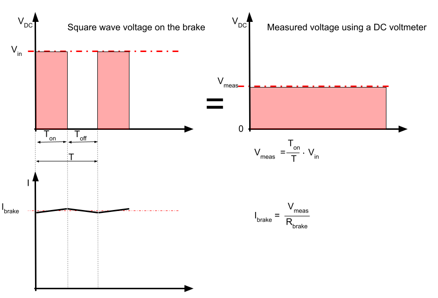
Example
V in (Input DC voltage) = 48 V DC
Brake switching frequency = 16 KHz
Brake hold voltage = 24 V
Brake resistance = 50 Ω


Attention
Applying more voltage to the brake than required will increase the brake temperature and damage the brake.
Danger
If the brake overheats while it’s released, the internal deformations might block the brake in the release state!
Measuring the brake current can be done with a DC ampere meter and measuring the brake DC voltage is possible with a common DC voltmeter.
The image below shows a non-safety brake circuit. Measuring the non-safety brake voltage can be done by connecting the voltmeter probe to the brake output (phase D on SOMANET Node) and ground.
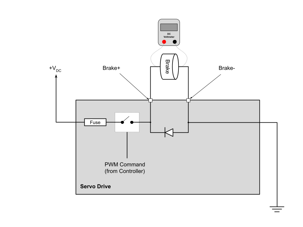
Note
The brake or a similar electrical load has to be connected to the brake outputs when measuring the output voltage. Without a load, the multimeter will show an incorrect input DC voltage!
The image below shows the safety brake circuit. The PWM signal is connected to a switch that is connected to Ground (GND). So for controlling the voltage level, it is generating a PWM signal on the GND side.
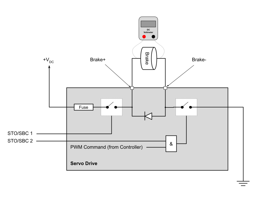
Note
The PWM signal is generated on the Brake- side.
For measuring the safety brake output voltage, B+ and B- must be connected to the voltmeter. Measuring the voltage between B+ and GND or B- and +V In will result in a wrong value.
Note
The brake or a similar electrical load has to be connected to the brake outputs when measuring the output voltage. Without a load, the multimeter will show an incorrect input DC voltage.
