- Hardware Manuals
- Commissioning and Tuning Guide
- Software Reference
- Resources
Using a gear can cause inaccuracy if the only encoder is positioned on the motor shaft.
A second encoder can be attached to the output shaft after the gear for an optimized position control.
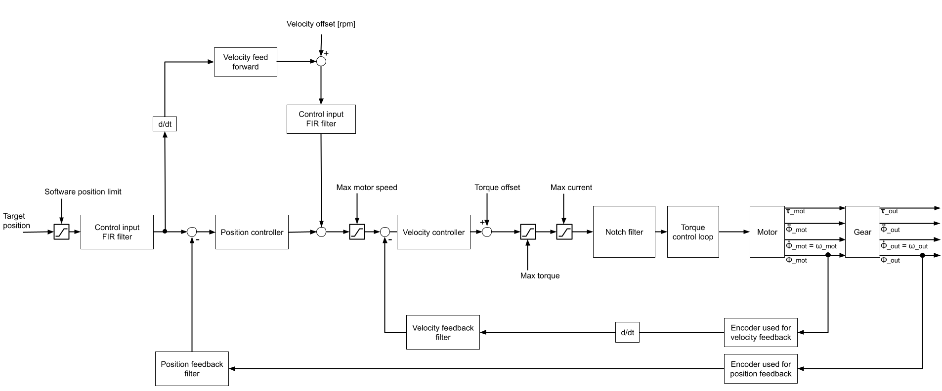
This section shows exemplary how the cascaded position controller can be configured for a dual encoder setup.
Note
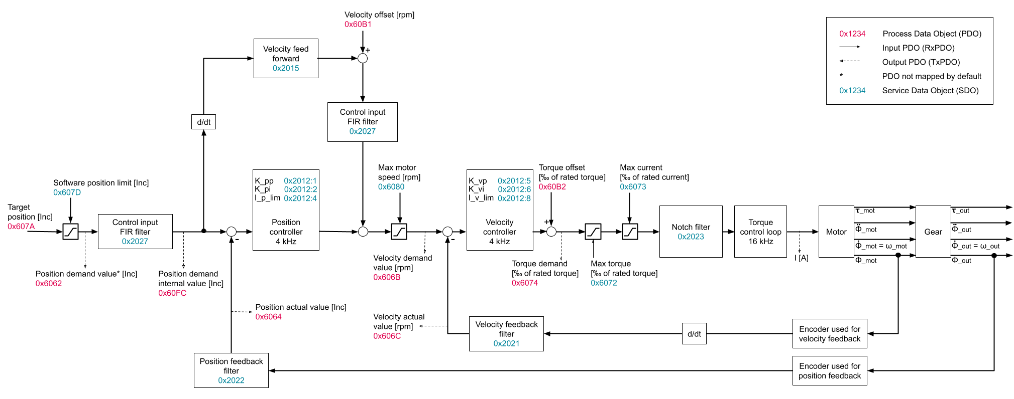
The specified units of the PDOs are valid only for the default unit configuration.
If user defined velocity(e.g. mRPM, rad/s) or position units are configured, they will be used instead.
Additionally, in this particular configuration, the following objects: 0x606C Velocity actual value, 0x60B1 Velocity offset and 0x606b Velocity demand value are defined in the gearbox output reference frame, not in the motor frame.
See more about the velocity reference frame in the Migration Guide
Attention
The velocity FIR filter is before velocity feed forward until firmware 5.0.3! Only in the soon-to-be-released firmware 5.0.4 it will be at the shown position.
Set the encoder installed on the motor side (gear input shaft) to Commutation and Velocity functions.
Set the encoder at the gear output shaft to Position function.
More details on encoder configuration can be found here.
Ensure that the gear ratio is set correctly in object 0x6091.
Object for indicating the revolutions of motor and shaft
Values Kp, Ki and Kd for Torque Controller
Values Kp, Ki and Kd for Cascaded Position Controller (Both loops: Position and Velocity)
