- Hardware Manuals
- Commissioning and Tuning Guide
- Software Reference
- Resources
Digital input STO-SBC 1 |
Digital input STO-SBC 2 |
Internal fault |
Safety Statusword |
Error entry |
|---|---|---|---|---|
0 |
0 |
no |
1 |
|
0 |
1 |
no |
1 |
“SfeDilvd” |
1 |
0 |
no |
1 |
“SfeDilvd” |
1 |
1 |
no |
0 |
|
0 |
0 |
yes |
1 |
“SfeFault” |
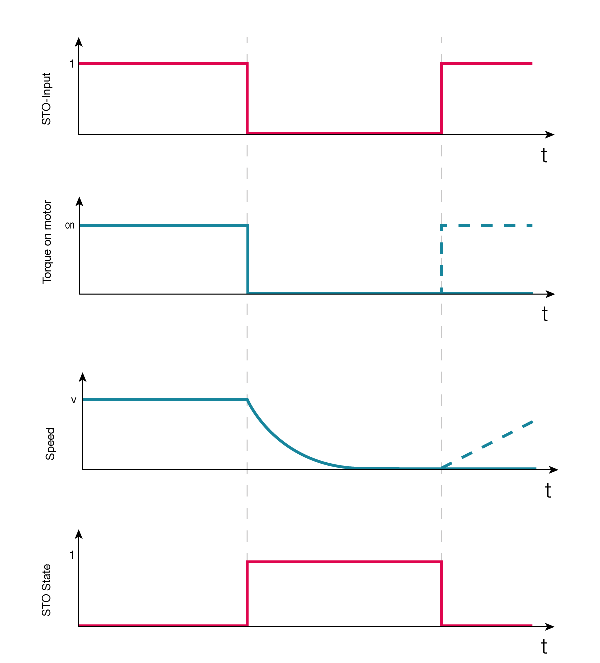
The safety circuit has two integrated diagnostic functions:
Comparing safety digital input statuses. The fault is activated after 100ms discrepancy of the STO-SBC inputs. In case a fault is detected, the servo drive will stop the motor and indicate a fault “SfeDilvd” in the Error Report object.
During the activation of the STO-SBC function the servo drive verifies that the two channels of the module are internally operating correctly. In case an internal fault is detected, the servo drive will stop the motor and indicate a fault “SfeFault” in the Error Report object.
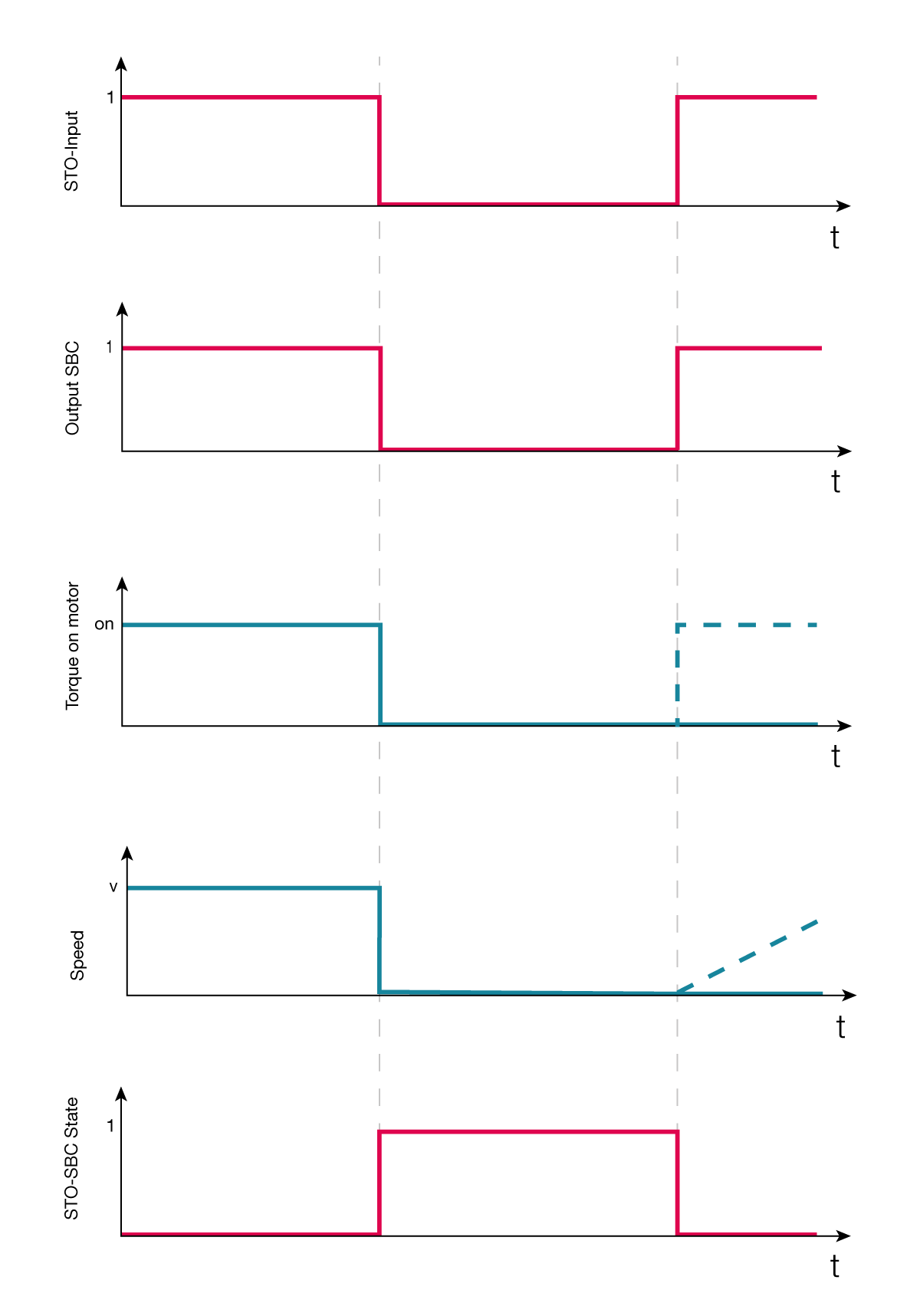
The STO-SBC feedback is a hardware feature that outputs a signal when both digital inputs have received the STO-SBC signal correctly.
The Safety Statusword indicates the current state of safety functions and Safety Digital Input Diagnostics shows the state of the safety inputs.
Index |
Name |
Descriptions |
|---|---|---|
0x6621 |
Safety Statusword |
Subindex:
STO/SBC status:
|
0x2611 |
Safety Digital Input Diagnostics |
Subindex:
Input 1/2:
|
Note
Using the SBC function while running the motor may damage the brake due to mechanical stress. During normal operation it is recommended to activate STO-SBC after the motor has come to a halt e.g. by introducing a delay with an external safety logic device such as a safety timer. This way an equivalent of SS1 with time monitoring is implemented.
Attention
The STO-function does not provide electrical isolation from the mains supply. If electrical changes need to be carried out on the system (e.g. modifying the motor cabling), the servo drive shall be completely isolated from mains supply with a mechanical switch.
STO-SBC use cases are not limited to the cases presented in this section:
The STO and SBC functions can be used for implementing the category 0 emergency stop function according to IEC 60204-1:2016.
Emergency stop function can be done
With an emergency stop switch connected directly to control the STO-SBC input signals
With an emergency stop relay + emergency stop switch. STO-SBC feedback signal can be utilized to make monitored manual start/restart
With safety PLC + emergency stop switch. STO-SBC feedback signal can be utilized to make monitored, manual start/restart
Please read the section about the working principle of the safety functions.
All cases above require correct behaviour from the controlling PLC (can be a non-safety PLC). After resetting the emergency stop function, a separate and deliberate action must be used to restart the system.
Attention
IEC 60204-1:2016 requires “reset shall not initiate a restart” regarding emergency stop.
STO and SBC function can be used when power removal is required to prevent an unexpected start-up according to ISO 14118. A lockable safety switch for activating the STO-SBC function is required.
The function “Prevention of unexpected start-up” can be used for system maintenance activities (e.g. Repairing/cleaning activities inside hazardous areas)
