- Hardware Manuals
- Commissioning and Tuning Guide
- Software Reference
- Resources
Commands are sent by the master to the drive with the controlword and the drive sends information about its state back to the master with the statusword.
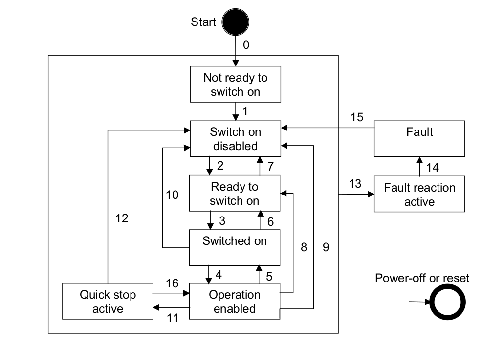
The controller is run through a state machine as defined in the CiA402 standard. The state changes are requested by the master using the controlword object 0x6040 and the slave will show the actual state in the statusword object 0x6041.
Only bits 0,1,2,3 and 7 in the controlword are used to change the state of the controller.
Only the first 7 bits of the statusword reflect the controller state.
The controlword and statusword should be used as defined in the CiA402 standard.
Some bits of controlword and statusword are dependent on the operation mode the drive is in, some bits of the statusword are also set by the manufacturer. Please check the section of each mode for details about which bits have which meaning:
The finite-state automaton (FSA) shows different states of the drive and how the transitions between them can be executed.
The basic bits (0-7) are identical in each mode.
The red marked bits 9 and 14-15 are not supported (N/A)
The yellow marked bits have a specific functions which depends on the mode the drive is currently in. See the documentation of the specific mode for details.
| 15 | 14 | 13 | 12 | 11 | 10 | 9 | 8 | 7 | 6 | 5 | 4 | 3 | 2 | 1 | 0 |
|---|---|---|---|---|---|---|---|---|---|---|---|---|---|---|---|
| ms | oms | oms | ila | tr | rm | ms | w | sod | qs | ve | f | oe | so | rtso | |
| N/A | operation mode specific bits | N/A | basic | ||||||||||||
The basic bits of the statusword indicate in which state the drive is:
State coding
Statusword |
FSA state |
|---|---|
xxxx xxxx x0xx 0000b |
Not ready to switch on |
xxxx xxxx x1xx 0000b |
Switch on disabled |
xxxx xxxx x01x 0001b |
Ready to switch on |
xxxx xxxx x01x 0011b |
Switched on |
xxxx xxxx x01x 0111b |
Operation enabled |
xxxx xxxx x00x 0111b |
Quick stop active |
xxxx xxxx x0xx 1111b |
Fault reaction active |
xxxx xxxx x0xx 1000b |
Fault |
Note
If bit 4 of the statusword is 1 that means that voltage is applied to the drive.
If bit 5 of the statusword is 0 that means that the drive is in quick stop active state.
If bit 7 of the statusword is 1 this indicates the presence of a warning condition.
If bit 11 is 1 this indicates that one of the control values has been limited. See table 1.
Bits 9, 14 and 15 are not used.
Legend
Abbr. |
Meaning |
|---|---|
rtso |
ready to switch on |
so |
switched on |
oe |
operation enabled |
f |
fault |
ve |
voltage enabled |
qs |
quick stop |
sod |
switch on disabled |
w |
warning |
ms |
manufacturer-specific |
rm |
remote |
tr |
target reached |
ila |
internal limit active |
oms |
operation mode specific |
ms |
manufacturer specific |
| Mode of operation | 13 | 12 | 11 | 10 | 8 |
|---|---|---|---|---|---|
| Profile Position | Following error | Set-point acknowledge | Internal limit Active | Target reached | N/A |
| Profile Velocity | N/A | Speed bit | |||
| Profile Torque | N/A | ||||
| Cyclic Synchronous Position | Target position ignored | ||||
| Cyclic Synchronous Velocity | Target velocity ignored | ||||
| Cyclic Synchronous Torque | Target Torque ignored | ||||
| Homing | Homing error | Homing attained |
The values that are limited by this bit differ in each mode:
Limiting object |
Limited value |
Operating modes |
|---|---|---|
Max torque (0x6072) |
Torque demand value (0x6074) |
All |
Max torque (0x6072) |
|
PT / CST |
Max. motor speed (0x6080) |
Velocity demand value (0x606B) |
CSP / PP |
Max. motor speed (0x6080) |
Profile velocity (0x6081) |
PP |
Max. motor speed (0x6080) |
Target velocity (0x60FF)Velocity offset (0x60B1). |
CSV / PV |
Software position limit (0x607D) |
Position demand value (0x6062) |
CSP/PP |
Legend:
PP: Profile Position
PV: Profile Velocity
PT: Profile Torque
CSP: Cyclic Synchronous Position
CSV: Cyclic Synchronous Velocity
CST: Cyclic Synchronous Torque
| 15 | 14 | 13 | 12 | 11 | 10 | 9 | 8 | 7 | 6 | 5 | 4 | 3 | 2 | 1 | 0 |
|---|---|---|---|---|---|---|---|---|---|---|---|---|---|---|---|
| ms | ms | ms | ms | ms | r | oms | h | fr | oms | oms | oms | eo | qs | ev | so |
| N/A | basic | operation mode specific bits | basic | ||||||||||||
Note
bits 9,10,11,12,13,14 and 15 are not used.
Legend:
Abbr. |
Meaning |
|---|---|
so |
switched on |
ev |
enable voltage |
qs |
quick stop |
eo |
enable operation |
oms |
operation mode specific |
fr |
fault reset |
h |
halt |
oms |
operation mode specific |
r |
reserved |
ms |
manufacturer specific |
State Coding
| Command | b7 | b3 | b2 | b1 | b0 | Transitions |
|---|---|---|---|---|---|---|
| Shutdown | 0 | x | 1 | 1 | 0 | 2,6,8 |
| Switch on | 0 | 0 | 1 | 1 | 1 | 3 |
| Switch on + enable operation | 0 | 1 | 1 | 1 | 1 | 3+4 (NOTE) |
| Disable voltage | 0 | x | x | 0 | x | 7,9,10,12 |
| quick stop | 0 | x | 0 | 1 | x | 7,10,11 |
| disable operation | 0 | 0 | 1 | 1 | 1 | 5 |
| enable operation | 0 | 1 | 1 | 1 | 1 | 4,16 |
| Fault reset | 1 | x | x | x | x | 15 |
| NOTE Automatic transition to Enable Operation state after executing SWITCHED ON state functionality. | ||||||
| Mode of operation | 8 | 7 | 6 | 5 | 4 |
|---|---|---|---|---|---|
| Profile Position | Halt | N/A | N/A | Change set immediately | New set-point |
| Profile Velocity | Halt | N/A | |||
| Profile Torque | Halt | N/A | |||
| Cyclic Synchronous Position | No Operation mode specific bits used | ||||
| Cyclic Synchronous Velocity | |||||
| Cyclic Synchronous Torque | |||||
| Homing | Halt | N/A | Homing operation start | ||