- Hardware Manuals
- Commissioning and Tuning Guide
- Software Reference
- Resources
An ABI encoder and a Hall sensor can be combined to function as a single encoder for commutation. This combines the benefits of a high resolution angle from the ABI encoder, with the absolute electrical position provided by the Hall sensor.
The Drive needs a Hall sensor and an ABI encoder connected at two different connectors, both must be properly configured.
The motor phases and the Hall pins have to be connected according to the Servo drive’s documentation.
The ABI commutation offset has to be found before this feature starts working.
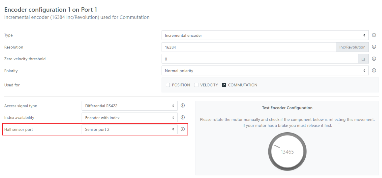
To configure the HALL+ABI feature, the incremental encoder needs to be configured for at least ”commutation” then specify the encoder port that the HALL sensor is connected to in the object “Encoder1 configuration Hall sensor port ”0x2110:23”
The drive will automatically use it on startup to avoid the index detection routine. There is no need for additional configuration of the hall sensor on encoder port 2.
Configuring the Hall additionally on port 2 will lead to a HwRsrcEr.
When the feature is started, the Hall sensor is sampled and it is checked if it’s in a valid state. If an invalid hall state [0, 0, 0] or [1, 1, 1] is found, an error ‘HallSeq’ is raised, and the connections should be checked.
Cable errors can lead to problems: if only one Hall sensor is disconnected or damaged, or if the phase signals are reversed, the problem will not be detected. Running the motor with Hall set as the only Commutation sensor can be done to ensure the integrity and proper connection of the Hall signals before integrating the ABI encoder.
If no error is raised, the initial electrical angle is estimated based on the Hall sensors, and the Hall sensors are not sampled again. As soon as the incremental encoder passes the index, the service realigns the electrical angle to the formerly saved precise value.
