- Hardware Manuals
- Commissioning and Tuning Guide
- Software Reference
- Resources
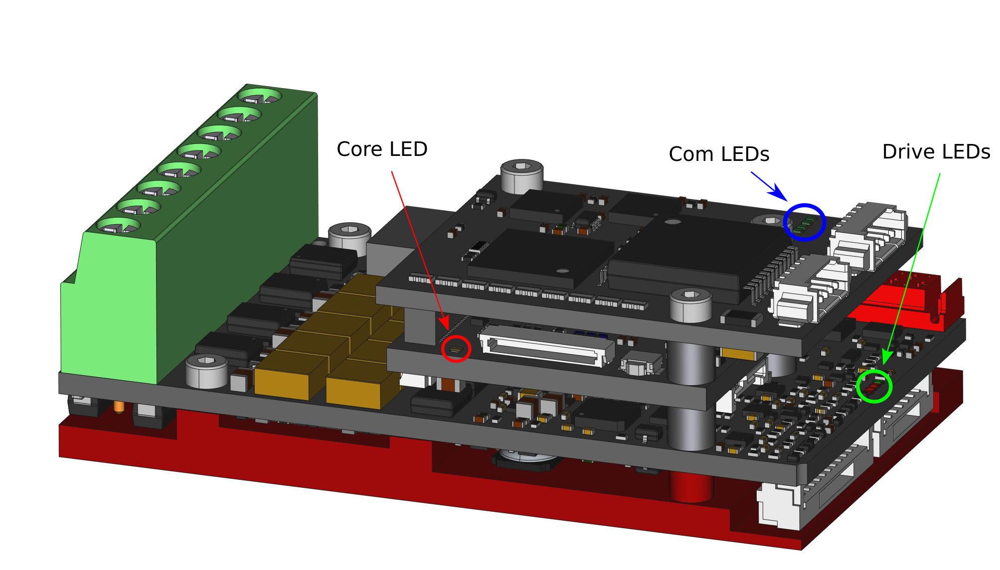
SOMANET Node has several LEDs that show the servo drive’s state or indicate errors.
| Symbol | Explanation |
|---|---|
| Off | |
| Constantly luminous | |
| Single flashes (1 pulse per second) | |
| Slow blinking (3 pulses per second) | |
| Fast blinking (10 pulses per second) | |
| Two colored behavior: One part of the LED is constantly luminous, the other is blinking slowly (3 pulses per second) | |
| Two colored behavior: One part of the LED is constantly luminous, the other is blinking fast (10 pulses per second) |
The tri-color LED is used by the firmware to indicate internal status and errors. It provides an overview of the firmware state at a glance to quickly see whether a drive is operating nominally.
| CiA 402 State | ||||||||
|---|---|---|---|---|---|---|---|---|
| Not Ready to Switch On | Switch on Disabled | Ready to Switch On | Switched On | Operation Enabled | Quick Stop | Fault and Fault Reaction | ||
| EtherCAT State | BOOT | |||||||
| INIT | ||||||||
| PREOP | ||||||||
| SAFEOP | ||||||||
| OP | ||||||||
Signals that are shown when the Bootloader is active:
| Bootloader State | No Fault (firmware exists) |
Fault (no firmware exists) |
|---|---|---|
| Idle | ||
| Operation in progress |
Note
If your servo drive is running Bootloader v1.0 you may find the LED fading in rainbow colors indicating that the bootloader is active.
The four LEDs on the Drive module show Hardware Errors.
| LED 1: Red | LED 2: Red | LED 3: Red | LED 4: Green | Explanation |
|---|---|---|---|---|
| No error | ||||
| Watchdog ticks fault | ||||
| Dead-time fault Phase A | ||||
| Dead-time fault Phase B | ||||
| Dead-time fault Phase C | ||||
| Dead-time fault Phase D | ||||
| Over-current in Phase A / Phase B / DC-bus | ||||
| Over-voltage / Under-voltage / Over-temperature |
Details about these errors and remedies can be found here: Error Report Object
Signals on the Com LED are required for EtherCAT conformity.
| LED 1: OUT: ACT | LED 2: OUT: LINK | LED 3: IN: ACT | LED 4: IN: LINK |
|---|---|---|---|
| |
|
|
|
