- Hardware Manuals
- Commissioning and Tuning Guide
- Software Reference
- Resources
The following examples can be used as a guidance for implementing some of the most common safety functions. A risk and hazard analysis is required for each application to find necessary safety functionalities and the requirements for the safety functions.
STO and SBC function can be used when power removal is required to prevent an unexpected start-up according to ISO 14118. A lockable safety switch for activating the STO-SBC function is required.
The function “Prevention of unexpected start-up” can be used for system maintenance activities (e.g. Repairing/cleaning activities inside hazardous areas)
The STO and SBC functions can be used for implementing the category 0 emergency stop function according to IEC 60204-1:2016.
The Emergency stop function can be realized
With an emergency stop switch connected directly to control the STO-SBC input signals
With an emergency stop relay + emergency stop switch.
With safety PLC + emergency stop switch.
Please read the section about the working principle of the Safety circuit.
All cases above require correct behaviour from the controlling PLC. After releasing the emergency stop device, a separate and deliberate action must be used to restart the system (restarting can be done with a non-safety PLC).
Attention
IEC 60204-1:2016 requires “reset shall not initiate a restart” regarding emergency stop.
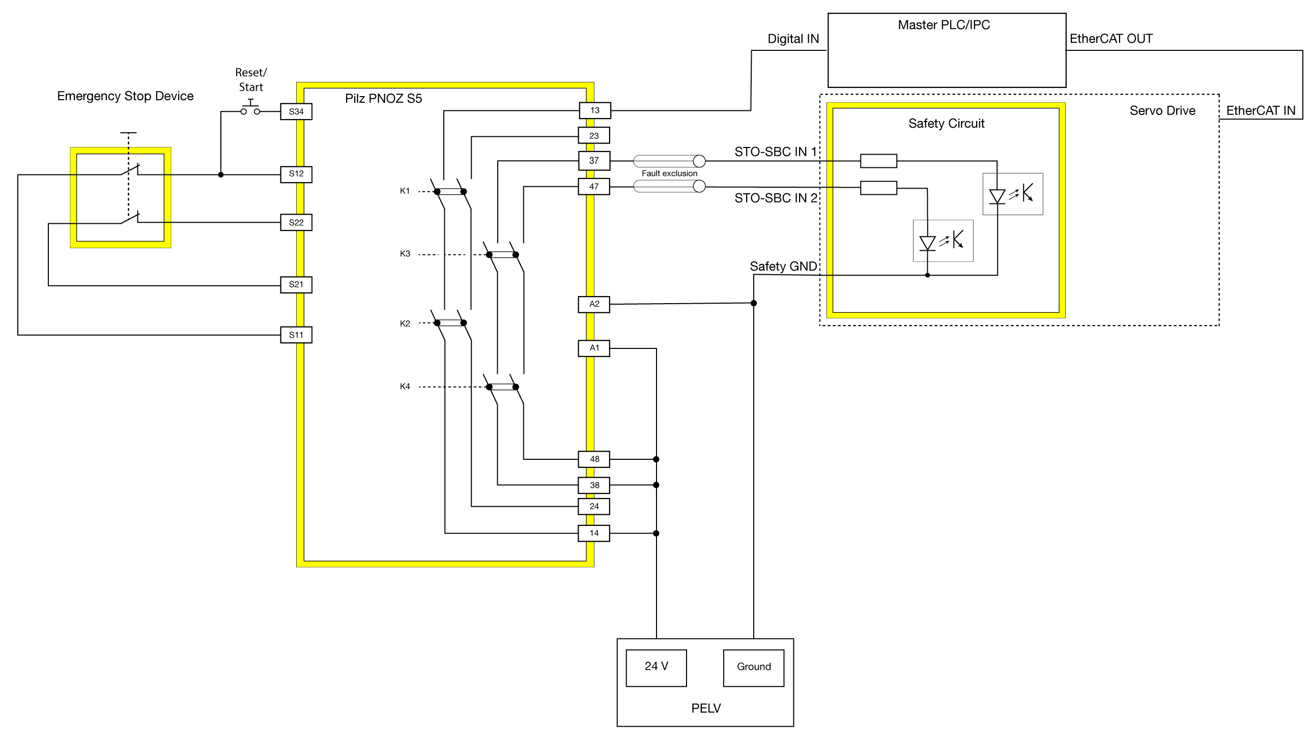
This example depicts the prerequisites and wiring for an emergency stop that fulfills the requirements according to
IEC 60204-1:2016 stop category 1 (a controlled stop with power available to the machine actuators to achieve the stop and then removal of power when the stop is achieved)
ISO 13849-1:2015 PLe, Cat. 3
IEC 61508:2010 SIL3
IEC 61800-5-2:2017 SS1 (Safe stop 1)
When the Emergency Stop Device (such as a push button or a light curtain) signals the execution of an emergency stop, two redundant sets of contactors are triggered:
K1/K2 gives immediately the signal to the Master PLC/IPC Digital Input. When the Digital Input is logical 0, the Master PLC/IPC shall request “quick stop” via EtherCAT Controlword 0x6040.
K3/K4 are triggered after a configurable time delay. During the time delay, the machine can be gracefully controlled to a stop before the activation of the SOMANET Node STO-SBC function.
SOMANET Node Safety
Safety Relay
Emergency stop device
Power supply (PELV)
Reset/Start switch
Note
It is necessary to use a momentary switch for Reset/Start function to fulfill the requirement regarding emergency stop “The reset of the emergency stop command shall not restart the machinery.”
Note
For a PLe, SIL 3 system please regard the requirements for fault exclusion between the STO-SBC 1 and STO-SBC 2 signals.
Calculate the PFHd (high demand mode) or PFD (low demand mode) of the whole safety function with the values given by the device’s safety manual. Verify that the PFD/PFHd of the safety function is sufficiently low for the desired safety level. You can find the values for SOMANET Node Safety here.
Test and validate the safety functions before taking the system is put into operation.
