- Hardware Manuals
- Commissioning and Tuning Guide
- Software Reference
- Resources
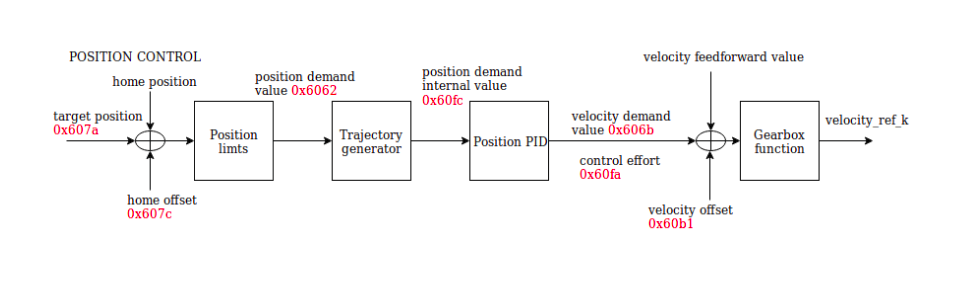
In Profile Position Mode a target position is applied to the trajectory generator. It is generating a position demand value for the position control loop taking into account the position limits. The trajectory generator computes the position demand internal value depending on the configured speed, starting acceleration and braking deceleration.
The following objects need to be configured for the position profile:
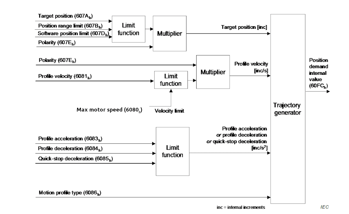
The trajectory generator receives the Target position 0x607A, taking into account the Position range limit 0x607B, the Software position limit 0x607D, as well as the Polarity 0x607E.
Note
Target position is limited by the Objects:
The output of the trajectory generator is the position demand internal value for the position PID..
To enable the mode, the value 1 (0001h) must be entered in object Modes of operation 0x6060. The object Op mode display 0x6061 can be used to check if the op mode has been set correctly.
The setting of set-points is controlled by the timing of the new set-point bit in the controlword as well as the set-point acknowledge bit in the statusword.
After a set-point is applied to the drive device, the control device signals that the set-point is valid by a rising the edge of the new set-point bit in the controlword. The drive device sets the set-point acknowledge bit in the statusword to 1, afterwards the drive device signals with the set-point acknowledge bit set to 0 its ability to accept new set-points.
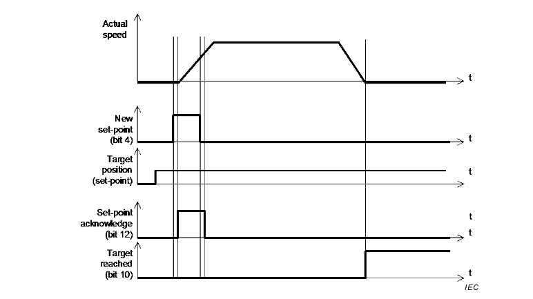
In order to execute the new set-point (new target value), bit 4 (new set-point) of the controlword needs to be changed from 0 to 1 (the profile reacts on the rising edge of the bit). The drive will respond with the rising edge of bit 12 (set-point acknowledge) of the statusword. The Single set-point method is used, which means that bit 5 of the controlword (Change set immediately) has to be set to 1.
Note
The profile position mode uses some bits of the controlword for mode specific purposes which are indicated in yellow. The figure shows the structure of the controlword. For the general structure and usage, please refer to our Application note on Status- and Controlword.
| 15-9 | 8 | 7-6 | 5 | 4 | 3-0 | |||
|---|---|---|---|---|---|---|---|---|
| N/A | Halt | N/A | Change set immediately | New set-point | basic | |||
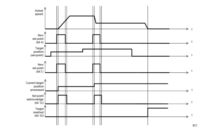
New set-point: On the rising edge, the drive will acknowledge the value of “target position” as a new set-point.
Change set immediately: Our drive supports only a single-set-point method of handling. Therefore, this bit has to be 1 before setting a new-point.
The new set-points will be executed immediately and won’t wait for the previous one to finish.
Attention
This bit 5 has to be set before or simultaneously with bit 4 `New set point`. If this bit is not set, the profile command will not be executed!
Halt: When the bit is activated, the drive will use the profile deceleration to put the motor’s shaft into a standstill position.
Note
The Halt bit is used to toggle the motion. When it is set to 1, the profile deceleration ramp will be used to reach 0 velocity. If it is set to 0 again, the demanded operation will be continued and the drive will accelerate using the profile acceleration ramp until the desired position has been reached.
The mode specific bits of the statusword can be used to monitor the performance of the operation. For further information please refer to the section on Control Supervision.
Objects related to bits 12 and 13 of the statusword:
| 15-14 | 13 | 12 | 11 | 10 | 9-8 | 7-0 | |||
|---|---|---|---|---|---|---|---|---|---|
| N/A | Following error | Set-point acknowledge | Internal limit active | Target reached | N/A | basic | |||
Internal limit active:
Target reached: the bit is set to 1 if the actual position stays in the window of the target position ± position window for a duration of position window time.
Set-point acknowledge: Is set to 1 when the drive acknowledges the rising edge on the new-set point bit of the controlword.
Following error: the bit is set to 1 If the actual position stays in the window of position demand value ± following error window for a duration of following error time out.
For more details check the object Following error actual value 0x60F4.
Note
If the position window is 0xFFFFFFFF position window monitoring will be switched off and the target reached bit will always be 0.
Example: Using the position profile
set the profile objects:
Profile Velocity 0x6081
Profile acceleration 0x6083
Profile deceleration 0x6084
Quick Stop deceleration 0x6085
set mode of operation to 1
Set target position
Switch the drive to “Operation Enabled”
Set bit 5 of the controlword:
Set bit 4 of the controlword:
The drive will acknowledge the new target position on the rising edge of bit 4 by activating the statusword bit 12 Set-point acknowledge for several cycles.
The motor will start rotating immediately.
Note
Setting the bits 4 and 5 of the controlword has to be done in the same order shown above or simultaneously.
Quick Stop deceleration 0x6085
The maximum possible speed of the Motor according to the data sheet.
Software position limit 0x607D
Following error timeout 0x6066
