- Hardware Manuals
- Commissioning and Tuning Guide
- Software Reference
- Resources
Attention
The magnetic encoder rings are densely packed with magnetic information. Any contact or even close proximity with external magnetic fields may destroy them permanently! Please consult our handling instructions for details
Assembling the encoder system in compliance with the following tolerances will allow reaching the specified accuracy after the calibration procedures.
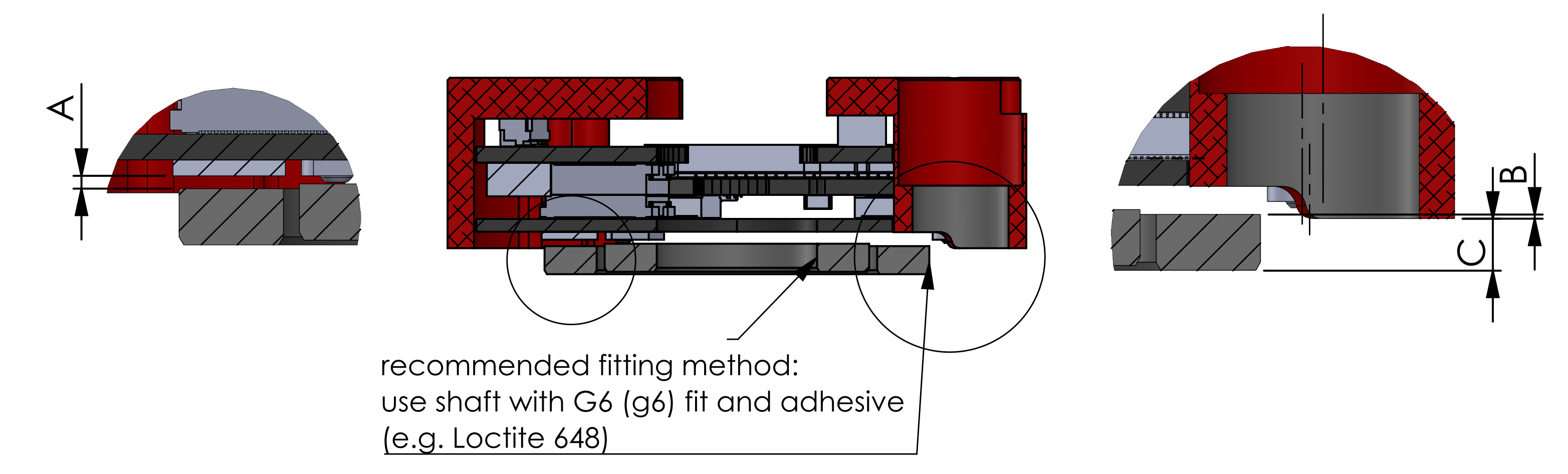
Considering the air gap between the ring and the encoder read head, the following dimensions should be kept during all modes of operation:
A is the distance between an encoder ring and an encoder read head (Air gap)
B is the distance between the top side of an encoder ring and the mounting surface of Circulo
C is the distance between the bottom side of an encoder ring and the mounting surface of Circulo
Important
It is not required to validate all the distances, as long as one of the values A, B or C is within its respective tolerance window.
Depending on the mounting situation and assembly process in the given application, it is typically easiest to use either distance B or C as a design point and also for validation.
The distance A is the actual air gap directly on the encoder, but it is difficult to measure it.
Value |
Inner Ring |
Outer Ring |
|---|---|---|
A [mm] |
0.5 ±0.20* |
0.8 ±0.20* |
B [mm] |
0.56 ±0.14 |
0.26 ±0.14 |
C [mm] |
2.94 ±0.13 |
3.24 ±0.13 |
* Note that dimension A and the respective tolerance are for informative purposes only.
This air gap is typically not accessible for measurement, nor can it be directly influenced by the design. Please use dimension B or C as design criteria.
It is possible to obtain an air gap feedback directly from the encoder chip in OBLAC Drives using the Magnetic ring distance checker feature. It can assist during the prototyping phase of the design. It computes the air gap based on the ring’s magnetic field strength and recommends the next action.
Value |
Inner Ring |
Outer Ring |
|---|---|---|
A [mm] |
0.4 ±0.20* |
0.75 ±0.20* |
B [mm] |
0.66 ±0.14 |
0.31 ±0.14 |
C [mm] |
2.84 ±0.13 |
3.19 ±0.13 |
* Note that dimension A and the respective tolerance are for informative purposes only.
This air gap is typically not accessible for measurement, nor can it be directly influenced by the design. Please use dimension B or C as design criteria.
It is possible to obtain an air gap feedback directly from the encoder chip in OBLAC Drives using the Magnetic ring distance checker feature. It can assist during the prototyping phase of the design. It computes the air gap based on the ring’s magnetic field strength and recommends the next action.
Parameter |
Value |
|---|---|
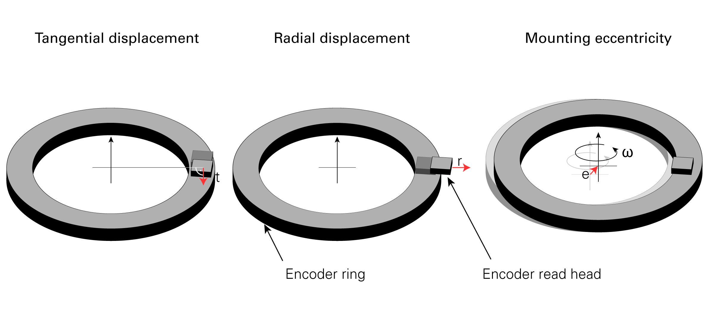
Radial displacement r |
max 0.3 mm |
Tangential displacement t |
max 0.3 mm |
Mounting eccentricity (radial runout) e |
max 0.1 mm |
This basically means sliding the encoder chip off the scanning track. Deviations within the permissible range increase the narrow angle error amplitude. This can be compensated by calibration. Moving the chip closer to the center of the ring will have the most effect due to a direct influence on the main positioning (Master) track. The other direction will mostly reduce the absolute position accuracy. If increased more than specified values, the chip might fail sensing the magnetic field and throw an error.
This displacement is along the direction of the disc rotation. It is typically less crucial than the radial displacement because the measured field doesn’t change as much along this axis. It reduces the absolute position accuracy.
The radial runout (or eccentricity) is a common inaccuracy of the rotating mechanical system. It has a direct effect on the encoder system in terms of performance and robustness. Hence, it should be as minimal as possible. Please refer to our encoder calibration guide for more information about influence of the radial runout on encoder performance.
Typically, the runout can be measured with a dial indicator pressed against the rotating component during rotation. Additionally, a periodic once-a-revolution distortion will be present in the velocity feedback signal.