- Hardware Manuals
- Commissioning and Tuning Guide
- Software Reference
- Resources
The system needs to know the specifications of each motor so that a motion command can be executed accordingly. There are specific Objects for configuring your Motor.
0x2003 Motor Specific Settings
Details for your motor specification.
The rated current of your Motor according to the data sheet.
The rated torque of your Motor according to the data sheet.
The maximal possible speed of your Motor according to the data sheet.
In some cases, the motor is equipped with a mechanical brake which can be released by applying electrical voltage to the brake’s terminals. The brake can be used to fix the motor shaft in a given position, for example for holding up a robot’s arm.
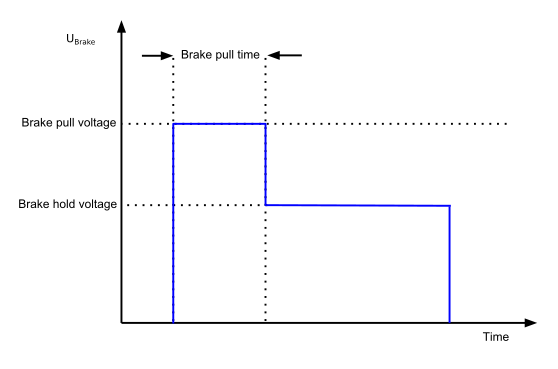
A configurable voltage is applied to the positive terminal of motor brake (It is assumed that the negative terminal of the brake is connected to Ground).
When the motion service allows motion, the specified “Pull voltage” will be generated for a configurable amount of time designated as “Pull time”. After this time period, the second voltage level (Hold voltage) will be applied to the brake terminals permanently. The brake hold voltage can be set to a lower value to save energy.
Note
Don’t set the hold voltage too low or you risk entering a marginally stable situation where any jerk can engage the brake.
Once the motion system leaves the state “operation enabled” the generated voltage is automatically dropped to Ground after the designated time “Brake engage delay” and the brake is mechanically activated.
Note
The brake release is an open loop system. After the brake pull time it is assumed that releasing was successful and the hold voltage is applied.
