- Hardware Manuals
- Commissioning and Tuning Guide
- Software Reference
- Resources
The OS command is a standard way of triggering actions or services on the drive by which cannot be adapted to a single SDO upload/download.
The following commands are currently available:
Command 0: Encoder register communication
Command 1: iC-MU calibration mode
Command 2: Open Loop Field Mode (OLFM)
Command 3: HRD streaming
Command 4: Motor phase order detection
Command 5: Commutation offset detection
Command 6: Open phase detection
Command 7: Pole pair detection
Command 8: Phase resistance measurement
Command 9: Phase inductance measurement
Command 10: Torque constant measurement
Command 13: Skipped cycles counter
Command 14: Ignore BISS status bits
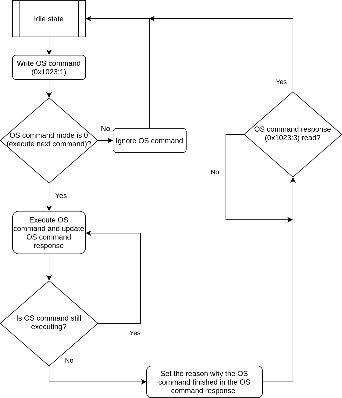
The OS command feature can be operated with the objects 0x1023 (OS command) and 0x1024 (OS command mode).
Select the command that should be used and start it by writing the desired value in subindex 1.
The status can be read in subindex 2.
The response can be fetched in subindex 3, it includes the status as written in subindex 2.
Note
To calculate the progress, please subtract 100 from the value of 0x1023:2.
| Subindex | Description | Data Type | Value |
|---|---|---|---|
| 1 | Command | OCTET_STRING | Byte 0:OS command ID
Byte 1-7:Service request data A write access to the subindex will execute the command |
| 2 | Status | UNSIGNED8 | 0:
last command completed, no errors, no response data.
1: last command completed, no errors, response data available 2: last command completed, error, no response data 3: last command completed, error, response data available 100-200: command executing with percentage (100 = 0%, 200 = 100%) 255: command executing (if percentage display is not supported) |
| 3 | Response | OCTET_STRING | Byte 0:
identical with subindex 2
Byte 1: unused Byte 2-7: Service response data |
Subindex 1 can’t be written until the command is finished and the response is read in subindex 3. If a command is written in that case anyway, it will be ignored and an OsCmdCol error will be raised.
The status of the command can be read in Subindex 2 and is also available in the first byte of subindex 3.
Note
It is recommended to read the status from the first byte of subindex 3 instead of subindex 2 because reading subindex 2 when a command is finished will not make subindex 1 writable again. The subindex 3 has to be read at least once after writing, before the next write command can be performed.
Both subindex 1 and subindex 3 are octet strings of size 8.
Byte 0 of the subindex 1 is used to choose the command that shall be executed.
The rest of the bytes are used to specify the parameters of the command, so they are command specific.
Byte 0 of the subindex 3 shows the status of the command. Depending on its value the rest of bytes on that subindex differ:
If the command is in progress (byte 0 is 100-200 or 255) or completed with no response data (byte 0 is 0 or 2), no other bytes will be set.
If the command is completed with no errors and with response data (byte 0 is 1), command specific bytes will be set starting at byte 2.
If the command is completed with errors and with response data (byte 0 is 3), byte 2 will be the OS error code (see below) and command specific bytes will be set starting at byte 3.
The following table shows all the valid responses (subindex 3) that any OS command might respond with. Grey table cells mean: these bytes are optional.
| Description | Byte 0 (Status) |
Byte 1 | Byte 2 | Byte 3 | Byte 4 | Byte 5 | Byte 6 | Byte 7 |
|---|---|---|---|---|---|---|---|---|
| Command in progress (with percentage) | 100 - 200 | ⦁ | ⦁ | ⦁ | ⦁ | ⦁ | ⦁ | ⦁ |
| Command in progress (without percentage) | 255 | ⦁ | ⦁ | ⦁ | ⦁ | ⦁ | ⦁ | ⦁ |
| Command completed without errors and without response | 0 | ⦁ | ⦁ | ⦁ | ⦁ | ⦁ | ⦁ | ⦁ |
| Command completed without errors and with response | 1 | ⦁ | Data | Data | Data | Data | Data | Data |
| Command completed with error and without response | 2 | ⦁ | ⦁ | ⦁ | ⦁ | ⦁ | ⦁ | ⦁ |
| Command completed with error and response | 3 | ⦁ | OS error code (see below) |
Data | Data | Data | Data | Data |
Indicates the reason of an error when the current command is completed with errors and with response data (status is 3).
Note
Error codes 0 - 8 are command specific, while error codes 251 - 254 are general error codes.
The command-specific OS error codes will be explained in detail in the corresponding section.
General OS error codes:
Unsupported command: the command ID received doesn’t exist.
Command timeout: A request to execute an OS command or to abort it was not acknowledged by any downstream service after 5s.
Command aborted: The abort action triggered by the user was successful.
Command not allowed: Certain commands can execute only under certain conditions (in a specific operation mode for example). This error code will be used to signal that these conditions are not met.
| OS Command # | |||||||||||
|---|---|---|---|---|---|---|---|---|---|---|---|
| 0 | 1 | 2 | 3 | 4 | 5 | 6 | 7 | 8 | 9 | 10 | |
| OS error code 0 | Invalid response | ⦁ | ⦁ | Initialization error | ⦁ | ⦁ | Open terminal A |
Current ampl. error | ⦁ | ||
| OS error code 1 | Register not allowed | ⦁ | ⦁ | Streaming error |
⦁ | ⦁ | Open terminal B | ⦁ | ⦁ | ⦁ | ⦁ |
| OS error code 2 | ⦁ | ⦁ | ⦁ | Duration value |
⦁ | ⦁ | Open terminal C | ⦁ | ⦁ | ⦁ | ⦁ |
| OS error code 3 | ⦁ | ⦁ | ⦁ | Data index value | ⦁ | ⦁ | Open FET A high | ⦁ | ⦁ | ⦁ | ⦁ |
| OS error code 4 | ⦁ | ⦁ | ⦁ | Action value | ⦁ | ⦁ | Open FET A low | ⦁ | ⦁ | ⦁ | ⦁ |
| OS error code 5 | ⦁ | ⦁ | ⦁ | ⦁ | ⦁ | ⦁ | Open FET B high | ⦁ | ⦁ | ⦁ | ⦁ |
| OS error code 6 | ⦁ | ⦁ | ⦁ | ⦁ | ⦁ | ⦁ | Open FET B low | ⦁ | ⦁ | ⦁ | ⦁ |
| OS error code 7 | ⦁ | ⦁ | ⦁ | ⦁ | ⦁ | ⦁ | Open FET C high | ⦁ | ⦁ | ⦁ | ⦁ |
| OS error code 8 | ⦁ | ⦁ | ⦁ | ⦁ | ⦁ | ⦁ | Open FET C low | ⦁ | ⦁ | ⦁ | ⦁ |
| … | (reserved for future use) | ||||||||||
| OS error code 251 | Command not allowed | ||||||||||
| OS error code 252 | Command aborted | ||||||||||
| OS error code 253 | Command timeout | ||||||||||
| OS error code 254 | Unsupported command | ||||||||||
This object is only used to abort the current command when value 0x03 is written. Otherwise (value 0x00 is written as a default) the next command is executed immediately.
| Value | Description |
|---|---|
| 0x00 | Execute the next command immediately (default) |
| 0x03 | Abort the current command and all commands in the buffer |
This object is write-only.
Writing 0 to this object will enable “Execute the next command immediately”, which is the default mode. In this mode, new OS commands will be executed as described above.
Writing 3 to this object will abort the currently executing command. Once the command is aborted successfully, the status “last command completed, error, response data available” (3) will be sent by the slave, and the OS error code (which will be explained in more detail later) in byte 2 of the response will signal the command abortion. If there is no command in progress, this write operation will be ignored.
The drive only accepts OS commands when the OS command state is idle, which means that the last command was completed and the response was read from 0x1023:3. Otherwise the OS command will be ignored, and the drive will enter the Fault CiA402 state (error report description will be OsCmdCol, which stands for OS command collision).
If subindex 0x1024:0 is not 0, the OS command will be ignored and discarded and no error will be raised.
Whenever an OS command is sent, the status will change from 0, 1, 2 or 3 to 255 immediately to ensure that the correct response is received.
At any point while a command is in progress, that command can be aborted writing 3 to the object 0x1024.
This command is used for reading or writing registers from a BiSS encoder.
Note
For more information about how BiSS register communication works, please refer to the official BiSS-C Interface Protocol Description.
The values in 0x1023:1 for this command are as follows:
| Byte | Bit 7 | Bit 6 | Bit 5 | Bit 4 | Bit 3 | Bit 2 | Bit 1 | Bit 0 |
|---|---|---|---|---|---|---|---|---|
| 0 | 0 | |||||||
| 1 | ⦁ | Encoder ordinal | ||||||
| 2 | Slave address / ID (0) | ⌝R/W | ||||||
| 3 | Register address | |||||||
| 4 | Register write value | |||||||
A value of 1 will select the Encoder 1 (which is the encoder configured in 0x2110), a value of 2 will select Encoder 2 (which is the encoder configured in 0x2112).
Value |
Encoder |
|---|---|
1 |
Encoder 1 |
2 |
Encoder 2 |
Slave address: selects the address of the slave to read (BiSS protocol level). This value must always be 0.
¬R/W: Selects the direction of the command: 0 for reading a register, 1 for writing it.
Register address: Register to be read/written.
Register write value: Value to write to the register. This is only used if the parameter ¬R/W is set to 1.
| Description | Byte 0 | Byte 1 | Byte 2 | Byte 3 | Byte 4 | Byte 5 | Byte 6 | Byte 7 |
|---|---|---|---|---|---|---|---|---|
| Command in progress (without percentage) | 255 | ⦁ | ⦁ | ⦁ | ⦁ | ⦁ | ⦁ | ⦁ |
| Command completed without errors and with response | 1 | ⦁ | Register value | ⦁ | ⦁ | ⦁ | ⦁ | ⦁ |
| Command completed with error and response | 3 | ⦁ | OS error code | ⦁ | ⦁ | ⦁ | ⦁ | ⦁ |
Status 255: The command is in progress.
Status 1: The command was finished successfully. The register value is the value read/ written from/to the selected register.
Status 3: The command has finished unsuccessfully. The error code will be sent, either as a general OS error code or a command-specific OS error code:
| OS error code | Error name | Error description |
|---|---|---|
| 0 | Invalid response | There was an error while executing the BiSS register transaction. This can be caused by
|
| 1 | Register not allowed | The register can’t be read given the current configuration. Currently the only registers that are not allowed to read are the iC-MU I2C registers (range 0x5B-0x6F) in Internal encoder 1 of Circulo if multiturn is disabled. If this happens, it can be avoided by setting the subindex "Status bits active value" to "Status bits ignored". |
To write the value 0x08 in register 0x11 of the encoder configured as Encoder 2, the bytes in 0x1023:1 should be set like this:
Byte |
Value |
|---|---|
0 |
0 |
1 |
2 |
2 |
1 |
3 |
0x11 |
4 |
0x08 |
In the terminal the following command can be used:
ethercat download 0x1023 1 0x0811010200 --type int64
Note
This command can only be used with IgH EtherCAT Master for Linux
To fetch the response, the following command should be entered:
ethercat upload 0x1023 3 --type int64
This value should be returned: 0x0000000000080001 (Status 1, with a confirmation of the written register value).
This command is used to be able to set a particular BiSS mode when using an iC-MU encoder, which is mostly used for iC-MU calibration. The following modes are supported:
Configuration mode: the BiSS service reads the encoder normally but it only uses the bits for register communication and discards the rest, so the encoder data is not updated. This also means BisCrc error is not raised while in this mode.
Raw mode: The BiSS service reads the encoder assuming it was correctly configured for raw mode. It continues calculating all the encoder data but in addition to that it also average of the raw data and makes it available in object 0x2704 User MISO like this:
Bit 31-28 27-14 16-0 0 Nonius count Master count
Standard mode: The BiSS service clocks the encoder normally.
When transitioning from any mode to Configuration mode, the current position is saved. When switching to Raw mode, this saved position will be used as a starting point for the position calculation, because the raw data is relative. This means that the motor should not be moved while in Configuration mode if we plan to switch to Raw mode after.
Values in 0x1023:1 for this command:
Byte |
Bit 7 |
Bit 6 |
Bit 5 |
Bit 4 |
Bit 3 |
Bit 2 |
Bit 1 |
Bit 0 |
|---|---|---|---|---|---|---|---|---|
0 |
1 |
|||||||
1 |
Mode enable |
Encoder ordinal |
||||||
Mode enable: select the iC-MU calibration mode.
Value
Mode
0
Configuration mode
1
Raw mode
2
Standard mode
A value of 1 will select the Encoder 1 (which is the encoder configured in 0x2110), a value of 2 will select Encoder 2 (which is the encoder configured in 0x2112).
Value |
Encoder |
|---|---|
1 |
Encoder 1 |
2 |
Encoder 2 |
Possible responses of this command:
| Description | Byte 0 | Byte 1 | Byte 2 | Byte 3 | Byte 4 | Byte 5 | Byte 6 | Byte 7 |
|---|---|---|---|---|---|---|---|---|
| Command in progress (without percentage) | 255 | ⦁ | ⦁ | ⦁ | ⦁ | ⦁ | ⦁ | ⦁ |
| Command completed without errors and without response | 0 | ⦁ | ⦁ | ⦁ | ⦁ | ⦁ | ⦁ | ⦁ |
| Command completed with error and without response | 2 | ⦁ | ⦁ | ⦁ | ⦁ | ⦁ | ⦁ | ⦁ | Command completed with error and response | 3 | ⦁ | OS error code | ⦁ | ⦁ | ⦁ | ⦁ | ⦁ |
Status 255: The command is in progress.
Status 0: The command was finished successfully.
Status 2: The command couldn’t be executed on the sensor. The received Mode enable value is unknown.
Status 3: This command doesn’t have any command-specific OS error code, so this status will only happen when a general OS error code occurs.
Configuring raw mode on encoder configured as Encoder 1:
Enable Configuration mode to freeze the current absolute position.
To change Internal encoder 1 of Circulo to Configuration mode, the bytes in 0x1023:1 need to be set like this:
Byte
Value
0
1
1
1
In the terminal the following command can be used:
ethercat download 0x1023 1 0x0101 --type int64To fetch the response, enter the following command:
ethercat upload 0x1023 3 --type int64Which should return 0x0000000000000000 (Status 0).
Use OS command 0 to configure Encoder 1 to output raw mode. Check the iC-MU datasheet for more information.
Enable Raw mode.
To change Encoder 1 to Raw mode, the bytes in 0x1023:1 need to be set like this:
Byte
Value
0
1
1
9
In the terminal the following command can be used:
ethercat download 0x1023 1 0x0901 --type int64To fetch the response, enter the following command:
ethercat upload 0x1023 3 --type int64Which should return 0x0000000000000000 (Status 0).
This command is used to be able to configure the settings of the Open Loop Field Mode (OLFM) profiler. The following configuration can be set by using this OS command:
Parameters related to the profiler of the electrical angle:
Starting electrical angle [mrad]
Ending electrical angle [mrad]
Maximum electrical rotational speed [rad / s]
Electrical rotational acceleration [rad / s²]
Parameters related to the profiler of the magnetic field length:
Starting length [per thousand rated current]
Ending length [per thousand rated current]
Increasing length rate [per thousand rated current / s]
Once the configurations of OLFM profiler are set, the user can put the drive in the corresponding OLFM op_mode (The op_mode for OLFM operation is -3), and by enabling the operation the Drive will generate a magnetic field according to the settings of its profiler. More information about this mode can be found in [Missing link].
Values in 0x1023:1 for this command:
Bit 7 |
Bit 6 |
Bit 5 |
Bit 4 |
Bit 3 |
Bit 2 |
Bit 1 |
Bit 0 |
|
|---|---|---|---|---|---|---|---|---|
Byte 0 |
2 |
|||||||
Byte 1 |
Parameter index |
|||||||
Byte 2 |
Parameter value [MSB] |
|||||||
Byte 3 |
Parameter value [MSB-1] |
|||||||
Byte 4 |
Parameter value [MSB-2] |
|||||||
Byte 5 |
Parameter value [LSB] |
|||||||
Parameter index: Selects the parameter that shall be configured.
Value |
Parameter and units |
|---|---|
0 |
Starting electrical angle [mrad] |
1 |
Ending electrical angle [mrad] |
2 |
Maximum electrical rotational speed [rad / s] |
3 |
Electrical rotational acceleration [rad / s²] |
4 |
Starting length [per thousand rated current] |
5 |
Ending length [per thousand rated current] |
6 |
Increasing length rate [per thousand rated current / s] |
Parameter value: The value to set the selected parameter to. The maximum size for the value is 32 bits and Byte 5 is the least significant byte (LSB).
The possible responses of this command:
| Description | Byte 0 (Status) |
Byte 1 | Byte 2 | Byte 3 | Byte 4 | Byte 5 | Byte 6 | Byte 7 |
|---|---|---|---|---|---|---|---|---|
| Command in progress (without percentage) | 255 | ⦁ | ⦁ | ⦁ | ⦁ | ⦁ | ⦁ | ⦁ |
| Command completed without errors and without response | 0 | ⦁ | ⦁ | ⦁ | ⦁ | ⦁ | ⦁ | ⦁ |
| Command completed with error and without response | 2 | ⦁ | ⦁ | ⦁ | ⦁ | ⦁ | ⦁ | ⦁ |
| Command completed with error and response | 3 | ⦁ | OS error code | ⦁ | ⦁ | ⦁ | ⦁ | ⦁ |
Status 255: The command is in progress.
Status 0: The command was finished successfully.
Status 2: The command couldn’t be executed. The received Parameter index value is unknown.
Status 3: This command doesn’t have any command-specific OS error code (this status will only happen when a general OS error code occurs).
For setting the “Starting electrical angle [mrad]” to 1000, the parameter value should be converted to hexadecimal so that it is easier to split between multiple bytes. In this case, 1000 is 0x3E8.
Then we should set the bytes in 0x1023:1 like this:
Byte |
Value |
|---|---|
0 |
2 |
1 |
0 |
2 |
0 |
3 |
0 |
4 |
0x03 |
5 |
0xE8 |
In the terminal the following command can be used:
ethercat download 0x1023 1 0xe80300000002 --type int64
To fetch the response, enter the following command:
ethercat upload 0x1023 3 --type int64
Which should return 0x0000000000000000 (Status 0).
This command is used for streaming data into files. The data written to these files is in binary format.
Multiple files will be created if necessary, up to a maximum of 5 files.
Each of the files will have a maximum size of 8032 bytes
The files are named “hr_dataX.bin”, where X is a number starting at 0.
Two actions are supported for this command:
Configure stream: all previous HRD files are deleted from the filesystem, and the user configures the duration of the stream and the variable to stream. Deleting files can take up to 5 seconds in the worst case scenario.
Start stream: The stream is started with the previously sent configuration.
The values in 0x1023:1 for this command are as follows:
| Byte | Bit 7 | Bit 6 | Bit 5 | Bit 4 | Bit 3 | Bit 2 | Bit 1 | Bit 0 |
|---|---|---|---|---|---|---|---|---|
| 0 | 3 | |||||||
| 1 | - | Action | ||||||
| 2 | Data index | |||||||
| 3 | Duration in ms [MSB] | |||||||
| 4 | Duration in ms [LSB] | |||||||
Action: select the action to perform.
Value |
Action |
|---|---|
0 |
Configure stream |
1 |
Start stream |
Data index: select the data to be streamed. This value is only used when the selected Action is Configure stream (0).
Value |
Data |
Description |
|---|---|---|
0 |
Encoder raw data |
Record encoder raw data. The encoder should be set up first with OS command 1. |
Duration in ms: select the duration in milli-seconds of the stream. This value is only used when the Action is Configure stream (0). The maximum value for this parameter is 10000 ms.
| Description | Byte 0 (Status) |
Byte 1 | Byte 2 | Byte 3 | Byte 4 | Byte 5 | Byte 6 | Byte 7 |
|---|---|---|---|---|---|---|---|---|
| Command in progress (with percentage) | 100 - 200 | ⦁ | ⦁ | ⦁ | ⦁ | ⦁ | ⦁ | ⦁ |
| Command in progress (without percentage) | 255 | ⦁ | ⦁ | ⦁ | ⦁ | ⦁ | ⦁ | ⦁ |
| Command completed without errors and without response | 0 | ⦁ | ⦁ | ⦁ | ⦁ | ⦁ | ⦁ | ⦁ |
| Command completed with error and response | 3 | ⦁ | OS error code | ⦁ | ⦁ | ⦁ | ⦁ | ⦁ |
Status 100-200: The command to stream the data to a file (Action is 1) is in progress.
Status 255: The command to configure the stream (Action is 0) is in progress.
Status 0: The command has finished successfully.
Status 3: The command has finished unsuccessfully. The error code will be sent, either as a
command-specific OS error code:
OS error code |
Error name |
Error description |
|---|---|---|
0 |
Initialization error |
The command failed to initialize. |
1 |
Streaming error |
Something failed while streaming was in progress. |
2 |
Duration value |
The selected Duration value is larger than 10000 ms. |
3 |
Data index value |
The selected Data index is unknown. |
4 |
Action value |
The selected Action is unknown. |
Streaming encoder raw data into a file for 5 s:
Use OS command 0 and OS command 1 to configure the iC-MU to output raw data.
Configure the streaming:
To configure the stream first we need to convert the duration to hexadecimal so that it is easier to split between multiple bytes. In this case, 5000 is 0x1388.
The bytes in 0x1023:1 should be:
Byte
Value
0
3
1
0
2
0
3
0x13
4
0x88
In the terminal the following command can be used:
ethercat download 0x1023 1 0x8813000003 --type int64To fetch the response, enter the following command:
ethercat upload 0x1023 3 --type int64Which should return 0x0000000000000000 (Status 0).
Start the streaming.
The bytes in 0x1023:1 should be:
Byte
Value
0
3
1
1
In the terminal the following command can be used:
ethercat download 0x1023 1 0x0103 --type int64To fetch the response, enter the following command:
ethercat upload 0x1023 3 --type int64Which should return 0x0000000000000000 (Status 0).
This command is used to be able to detect the order of the motor phases, it is also the first step that is performed during Offset detection. When this command finishes successfully the found value is automatically written to the object 0x2003:5 Motor phases inverted.
This command can only be run when the operation mode is -2 (OPMODE_DIAGNOSTICS) and the CiA402 state is Operation enabled. If any of these conditions is not true during the execution of the command, it will be automatically finished. More information about this operation mode can be found in the Diagnostics opmode.
The values in 0x1023:1 for this command are as follows:
Bit 7 |
Bit 6 |
Bit 5 |
Bit 4 |
Bit 3 |
Bit 2 |
Bit 1 |
Bit 0 |
|
|---|---|---|---|---|---|---|---|---|
Byte 0 |
4 |
|||||||
Description |
Byte 0 |
Byte 1 |
Byte 2 |
Byte 3 |
Byte 4 |
Byte 5 |
Byte 6 |
Byte 7 |
|---|---|---|---|---|---|---|---|---|
Command in progress (without percentage) |
255 |
|||||||
Command completed without errors and with response |
1 |
Motor phase order |
||||||
Command completed with error and response |
3 |
OS error code |
Status 255: The command is in progress.
Status 1: The command was finished successfully. The detected motor phase order is written in byte 2.
Value
Motor phase order
0
Normal order
1
Inverted order
Status 3: This command doesn’t have any command-specific OS error code, so this status will only happen when a general OS error code occurs.
To measure the motor phase order of our setup, we would need to:
Switch to diagnostics mode, enter operation enable and disengage the brake if there is one. For details please refer to Diagnostics opmode.
Execute the OS command.
Set Byte 0 of 0x1023:1 to 4.
In the terminal the following command can be used:
ethercat download 0x1023 1 0x04 --type int64To fetch the response, enter the following command:
ethercat upload 0x1023 3 --type int64
If the Motor phase order is normal, the response would be 0x0000000000000001 (Status 0, Normal motor phase order).
If the Motor phase order is inverted, the response would be 0x0000000000010001 (Status 1, Inverted motor phase order).
This command is used to measure the commutation angle offset which is the second step in the Offset Detection procedure. The configuration of the procedure is taken from the already existing and previously used commutation offset objects in the object dictionary. When this command finishes successfully the found value is automatically written to the object 0x2001:0 Commutation angle offset, and the object 0x2009:1 State is set to OFFSET_VALID.
This command can only be run when the operation mode is -2 (OPMODE_DIAGNOSTICS) and the CiA402 state is Operation enabled. If any of these conditions is not true during the execution of the command, it will be automatically aborted. More information about this operation mode can be found in Diagnostics opmode.
For details about the different methods for Offset detection, refer to Commutation Offset Detection.
The values in 0x1023:1 for this command are as follows:
Bit 7 |
Bit 6 |
Bit 5 |
Bit 4 |
Bit 3 |
Bit 2 |
Bit 1 |
Bit 0 |
|
|---|---|---|---|---|---|---|---|---|
Byte 0 |
5 |
|||||||
Description |
Byte 0 |
Byte 1 |
Byte 2 |
Byte 3 |
Byte 4 |
Byte 5 |
Byte 6 |
Byte 7 |
|---|---|---|---|---|---|---|---|---|
Command in progress (without percentage) |
255 |
|||||||
Command completed without errors and with response |
1 |
Commutation angle offset [MSB] |
Commutation angle offset [LSB] |
|||||
Command completed with error and response |
3 |
OS error code |
Status 255: The command is in progress.
Status 1: The command was finished successfully. The measured angle offset is written in bytes 2 and 3.
Status 3: This command doesn’t have any command-specific OS error code, so this status will only happen when a general OS error code occurs.
To measure the commutation angle offset of our setup, we would need to:
Configure the Commutation offset detection parameters in the object 0x2009.
Switch to diagnostics mode, enter operation enable and disengage the brake if necessary. For details please refer to Diagnostics opmode.
Execute the OS command.
Set Byte 0 of 0x1023:1 to 5. In the terminal the following command can be used:
ethercat download 0x1023 1 0x05 --type int64To fetch the response, enter the following command:
ethercat upload 0x1023 3 --type int64In case the Commutation angle offset is 2035, this would return 0x0000000007F30001 (Status 1, 2035 is 0x7F3 in hexadecimal).
This command is used for detecting if one of the phases is open.
This command can only be run when the operation mode is -2 (OPMODE_DIAGNOSTICS) and the CiA402 state is Operation enabled. If any of these conditions is not true during the execution of the command, it will be automatically aborted. For details please refer to Diagnostics opmode.
The values in 0x1023:1 for this command are as follows:
Bit 7 |
Bit 6 |
Bit 5 |
Bit 4 |
Bit 3 |
Bit 2 |
Bit 1 |
Bit 0 |
|
|---|---|---|---|---|---|---|---|---|
Byte 0 |
6 |
|||||||
Description |
Byte 0 |
Byte 1 |
Byte 2 |
Byte 3 |
Byte 4 |
Byte 5 |
Byte 6 |
Byte 7 |
|---|---|---|---|---|---|---|---|---|
Command in progress (without percentage) |
255 |
|||||||
Command completed without errors and without response |
0 |
|||||||
Command completed with error and response |
3 |
OS error code |
Status 255: The command is in progress.
Status 0: The command was finished successfully, no open motor phase was detected.
Status 3: The command was finished unsuccessfully. Either a general OS error code or a command-specific OS error code will be sent.
OS error code |
Error name |
Error description |
|---|---|---|
0 |
Open terminal A |
Terminal A of the Drive is not connected |
1 |
Open terminal B |
Terminal B of the Drive is not connected |
2 |
Open terminal C |
Terminal C of the Drive is not connected |
3 |
Open FET A high |
Upper FET in leg A of the Drive is not conducting (open circuit fault) |
4 |
Open FET A low |
Lower FET in leg A of the Drive is not conducting (open circuit fault) |
5 |
Open FET B high |
Upper FET in leg B of the Drive is not conducting (open circuit fault) |
6 |
Open FET B low |
Lower FET in leg B of the Drive is not conducting (open circuit fault) |
7 |
Open FET C high |
Upper FET in leg C of the Drive is not conducting (open circuit fault) |
8 |
Open FET C low |
Lower FET in leg C of the Drive is not conducting (open circuit fault) |
To detect if any of the motor phases is open in our setup, we would need to:
Switch to diagnostics mode and enter operation enable. For details please refer to Diagnostics opmode.
Execute the OS command.
Set Byte 0 of 0x1023:1 to 6. In the terminal the following command can be used:
ethercat download 0x1023 1 0x06 --type int64To fetch the response, enter the following command:
ethercat upload 0x1023 3 --type int64
For example if terminal B is open this would return 0x0000000000010003 (Status 3, OS error code 1).
If no issue was found, this would return 0x0000000000000000 (Status 0).
This command is used to detect the amount of pole pairs that the connected motor has.
This command can only be run when the operation mode is -2 (OPMODE_DIAGNOSTICS) and the CiA402 state is Operation enabled. If any of these conditions is not true during the execution of the command, it will be automatically aborted. For details please refer to Diagnostics opmode.
The values in 0x1023:1 for this command are as follows:
Bit 7 |
Bit 6 |
Bit 5 |
Bit 4 |
Bit 3 |
Bit 2 |
Bit 1 |
Bit 0 |
|
|---|---|---|---|---|---|---|---|---|
Byte 0 |
7 |
|||||||
Description |
Byte 0 |
Byte 1 |
Byte 2 |
Byte 3 |
Byte 4 |
Byte 5 |
Byte 6 |
Byte 7 |
|---|---|---|---|---|---|---|---|---|
Command in progress (without percentage) |
255 |
|||||||
Command completed without errors and with response |
1 |
Number of pole pairs |
||||||
Command completed with error and response |
3 |
OS error code |
Status 255: The command is in progress.
Status 1: The command was finished successfully. The measured number of motor pole pairs is written in byte 2.
Status 3: The command was finished unsuccessfully. Either a general OS error code or a command-specific OS error code will be sent.
OS error code |
Error name |
Error description |
|---|---|---|
0 |
Current ampl. error |
Drive is not able to increase the amplitude of motor phase currents to the required value. This problem can happen due to limited V DC or high motor phase impedances |
For measuring the motor phase order:
Switch to diagnostics mode, enter operation enable and disengage the brake if there is one. For details please refer to Diagnostics opmode.
Execute the OS command.
Set Byte 0 of 0x1023:1 to 7. In the terminal the following command can be used:
ethercat download 0x1023 1 0x07 --type int64
To fetch the response, enter the following command:
ethercat upload 0x1023 3 --type int64
In case the motor has 3 pole pairs, this would return 0x0000000000030001 (Status 1).
This command is used to measure the phase resistance of the motor in mOhm.
This command can only be run when the operation mode is -2 (OPMODE_DIAGNOSTICS) and the CiA402 state is Operation enabled. If any of these conditions is not true during the execution of the command, it will be automatically aborted. For details please refer to Diagnostics opmode.
Values in 0x1023:1 for this command:
Bit 7 |
Bit 6 |
Bit 5 |
Bit 4 |
Bit 3 |
Bit 2 |
Bit 1 |
Bit 0 |
|
|---|---|---|---|---|---|---|---|---|
Byte 0 |
8 |
|||||||
Description |
Byte 0 |
Byte 1 |
Byte 2 |
Byte 3 |
Byte 4 |
Byte 5 |
Byte 6 |
Byte 7 |
|---|---|---|---|---|---|---|---|---|
Command in progress (without percentage) |
255 |
|||||||
Command completed without errors and with response |
1 |
Phase resistance [MSB] |
Phase resistance [MSB-1] |
Phase resistance [MSB-2] |
Phase resistance [LSB] |
|||
Command completed with error and response |
3 |
OS error code |
Status 255: The command is in progress.
Status 1: The command was finished successfully. The measured motor phase resistance is written in bytes 2, 3, 4 and 5.
Status 3: The command was finished unsuccessfully. Either a general OS error code or a command-specific OS error code will be sent.
OS error code |
Error name |
Error description |
|---|---|---|
0 |
Current ampl. error |
Unable to increase the current amplitude. |
To measure the motor phase resistance of our setup, we would need to:
Switch to diagnostics mode, enter operation enable and disengage the brake if there is one. For details please refer to Diagnostics opmode.
Execute the OS command.
Set Byte 0 of 0x1023:1 to 8. In the terminal the following command can be used:
ethercat download 0x1023 1 0x08 --type int64To fetch the response, enter the following command:
ethercat upload 0x1023 3 --type int64In case the motor phase resistance is 100000, this would return 0x0000000186A00001 (Status 1, 100000 is 0x186A0 in hexadecimal).
This command is used to measure the phase inductance of the motor in uH.
This command can only be run when the operation mode is -2 (OPMODE_DIAGNOSTICS) and the CiA402 state is Operation enabled. If any of these conditions is not true during the execution of the command, it will be automatically aborted. More information about this operation mode can be found in the Diagnostics opmode.
The values in 0x1023:1 for this command are as follows:
Bit 7 |
Bit 6 |
Bit 5 |
Bit 4 |
Bit 3 |
Bit 2 |
Bit 1 |
Bit 0 |
|
|---|---|---|---|---|---|---|---|---|
Byte 0 |
9 |
|||||||
Description |
Byte 0 |
Byte 1 |
Byte 2 |
Byte 3 |
Byte 4 |
Byte 5 |
Byte 6 |
Byte 7 |
|---|---|---|---|---|---|---|---|---|
Command in progress (without percentage) |
255 |
|||||||
Command completed without errors and with response |
1 |
Phase inductance [MSB] |
Phase inductance [MSB-1] |
Phase inductance [MSB-2] |
Phase inductance [LSB] |
|||
Command completed with error and response |
3 |
OS error code |
Status 255: The command is in progress.
Status 1: The command was finished successfully. The measured motor phase inductance is written in bytes 2, 3, 4 and 5.
Status 3: The command was finished unsuccessfully. Either a:ref:general OS error code<50_os_command_general_errors> or a command-specific OS error code will be sent.
OS error code |
Error name |
Error description |
|---|---|---|
0 |
Current ampl. error |
Unable to increase the current amplitude. |
To measure the motor phase inductance of our setup, we would need to:
Switch to diagnostics mode, enter operation enable and disengage the brake if there is one. For details please refer to Diagnostics opmode.
Execute the OS command.
Set Byte 0 of 0x1023:1 to 9. In the terminal the following command can be used:
ethercat download 0x1023 1 0x09 --type int64To fetch the response, enter the following command:
ethercat upload 0x1023 3 --type int64In case the motor phase inductance is 4000, this would return 0x0000000010940001 (Status 1, 4244 is 0x1094 in hexadecimal).
This command is used to measure the torque constant of the motor in mNm/A RMS.
This command can only be run when the operation mode is -2 (OPMODE_DIAGNOSTICS) and the CiA402 state is Operation enabled. If any of these conditions is not true during the execution of the command, it will be automatically aborted. More information about this operation mode can be found in Diagnostics opmode.
The values in 0x1023:1 for this command are as follows:
Bit 7 |
Bit 6 |
Bit 5 |
Bit 4 |
Bit 3 |
Bit 2 |
Bit 1 |
Bit 0 |
|
|---|---|---|---|---|---|---|---|---|
Byte 0 |
0x0A |
|||||||
Description |
Byte 0 |
Byte 1 |
Byte 2 |
Byte 3 |
Byte 4 |
Byte 5 |
Byte 6 |
Byte 7 |
|---|---|---|---|---|---|---|---|---|
Command in progress (without percentage) |
255 |
|||||||
Command completed without errors and with response |
1 |
Torque constant [MSB] |
Torque constant [MSB-1] |
Torque constant [MSB-2] |
Torque constant [LSB] |
|||
Command completed with error and response |
3 |
OS error code |
Status 255: The command is in progress.
Status 1: The command was finished successfully. The measured motor phase inductance is written in bytes 2, 3, 4 and 5.
Status 3: This command doesn’t have any command-specific OS error code, so this status will only happen when a general OS error code occurs.
For measuring the motor torque constant:
Switch to diagnostics mode, enter operation enable and disengage the brake if there is one. For details please refer to Diagnostics opmode.
Execute the OS command.
Set Byte 0 of 0x1023:1 to 10 (0xA). In the terminal the following command can be used:
ethercat download 0x1023 1 0x0A --type int64To fetch the response, enter the following command:
ethercat upload 0x1023 3 --type int64In case the motor torque constant is 1203210, this would return 0x000000125C0A0001 (Status 1, 1203210 is 0x125C0A in hexadecimal).
This command is used to check the number of firmware cycles skipped. It provides the value of an internal counter that keeps track of the number of skipped cycles.
The values in 0x1023:1 for this command are as follows:
Bit 7 |
Bit 6 |
Bit 5 |
Bit 4 |
Bit 3 |
Bit 2 |
Bit 1 |
Bit 0 |
|
|---|---|---|---|---|---|---|---|---|
Byte 0 |
0x0D |
|||||||
Byte 1 |
Firmware service |
|||||||
Explanation of the parameters:
Firmware service: select the action to perform.
Value |
Action |
|---|---|
0 |
Drive control service |
1 |
Motion control service |
The possible responses that this command will use are the following:
| Description | Byte 0 | Byte 1 | Byte 2 | Byte 3 | Byte 4 | Byte 5 | Byte 6 | Byte 7 |
|---|---|---|---|---|---|---|---|---|
| Command in progress (without percentage) | 255 | - | - | - | - | - | - | - |
| Command completed without errors and with response | 1 | - | Number of skipped cycles [MSB] | Number of skipped cycles [MSB-1] | Number of skipped cycles [MSB-2] | Number of skipped cycles [LSB] | - | - |
| Command completed with error and response | 3 | - | OS error code | - | - | - | - | - |
Status 255: The command is in progress.
Status 1: The command finished successfully. The number of skipped cycles is written in bytes 2, 3, 4 and 5.
Status 3: This command doesn’t have any command-specific OS error code, so this status will only happen when a general OS error code occurs.
To get the value of the skipped cycles counter of Motion control service:
Set Byte 0 of 0x1023:1 to 13 (0xD), and Byte 1 to 1.
In the terminal we can use the following command:
ethercat download 0x1023 1 0x010D --type int64
To fetch the response, we should type the following command:
ethercat upload 0x1023 3 --type int64
This will return a value, for example 23. If we run the command again after some time and we get for example 33, this will mean that 10 cycles were skipped in the timespan between both OS commands.
This command is used to ignore the BiSS status bits, so that they don’t raise a firmware warning or error.
In the case of Circulo, it also stops reading the iC-PVL STATUS register when multiturn is enabled.
The values in 0x1023:1 for this command are as follows:
Bit 7 |
Bit 6 |
Bit 5 |
Bit 4 |
Bit 3 |
Bit 2 |
Bit 1 |
Bit 0 |
|
|---|---|---|---|---|---|---|---|---|
Byte 0 |
0x0E |
|||||||
Byte 1 |
Encoder ordinal |
Trigger |
||||||
Explanation of the parameters:
Trigger: a value of 1 will ignore the status bits. A value of 0 will stop ignoring them, which is the default behavior of the firmware.
Encoder ordinal: select the target encoder for the command. A value of 1 will select Encoder 1 (which is the encoder configured in 0x2110), a value of 2 will select Encoder 2 (which is the encoder configured in 0x2112).
Value |
Encoder |
|---|---|
1 |
Encoder 1 |
2 |
Encoder 2 |
The possible responses that this command will use are the following:
Description |
Byte 0 |
Byte 1 |
Byte 2 |
Byte 3 |
Byte 4 |
Byte 5 |
Byte 6 |
Byte 7 |
|---|---|---|---|---|---|---|---|---|
Command in progress (without percentage) |
255 |
|||||||
Command completed without errors and without response |
0 |
|||||||
Command completed with error and response |
3 |
OS error code |
Status 255: The command is in progress.
Status 0: The command finished successfully.
Status 3: This command doesn’t have any command-specific OS error code, so this status will only happen when a general OS error code occurs.
If we want to ignore the BiSS status bits of Encoder 1 we should:
Set Byte 0 of 0x1023:1 to 14 (0xE), and Byte 1 to 3 (0b11). In the terminal we can use the following command:
ethercat download 0x1023 1 0x030E --type int64To fetch the response, we should type the following command:
ethercatupload 0x1023 3 --type int64Which should return 0x0000000000000000 (Status 0).
Selects, starts and reports the status of the command that should be used.
Orders the next command to be processed or aborts all commands.
