- Hardware Manuals
- Commissioning and Tuning Guide
- Software Reference
- Resources
Attention
For SIL 3, PL e, cat.3 it is required to send test pulses from the PLC to the output or to ensure fault exclusion for wiring “Short circuit between any two conductors” according to ISO 13849-2:2012 between signals STO-SBC 1 and STO-SBC 2
permanently connected (fixed) and protected against external damage, e.g. by cable ducting, armouring, OR
separate multicore cables, OR
within an electrical enclosure, OR
individually shielded with earth connection.
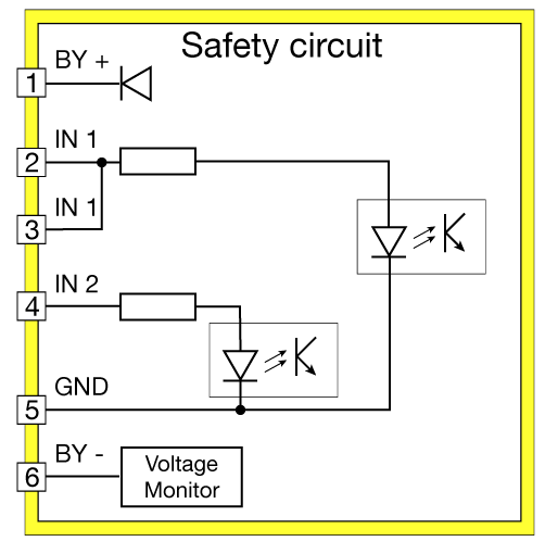
Pin# |
Designation |
Function |
Description |
|---|---|---|---|
1 |
BY+ |
Bypass+ |
Connect to BY- (Pin 6) to bypass STO/SBC |
2 |
IN1 |
STO/SBC input 1 |
Input 1 for STO/SBC |
3 |
IN1 |
STO/SBC input 1 |
Extra Pin for Input 1 |
4 |
IN2 |
STO/SBC input 2 |
Input 2 for STO/SBC |
5 |
GND |
Safety GND |
Must be isolated from main Ground |
6 |
BY- |
Bypass- |
Connect to BY+ (Pin 1) to bypass STO/SBC |
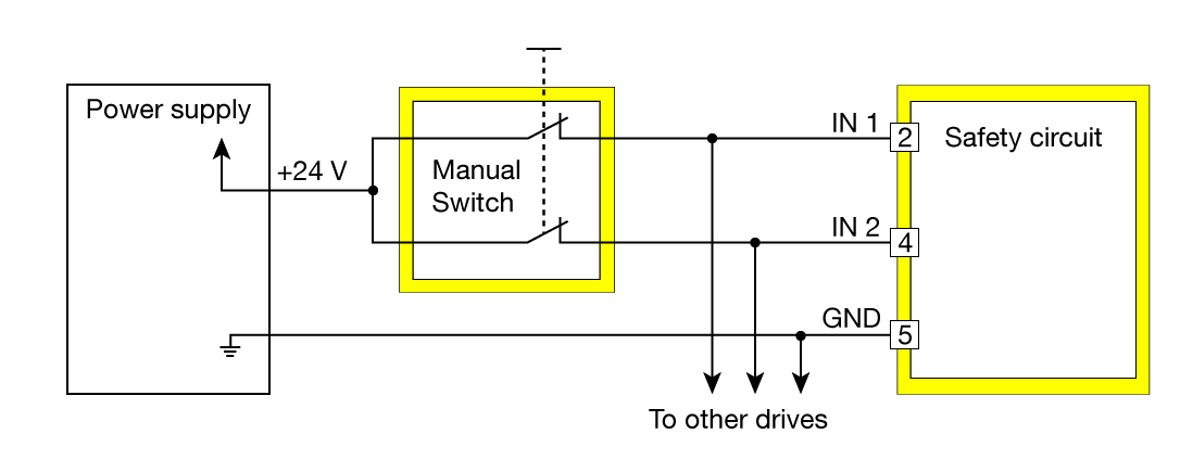
The wiring differs depending on the safety device used:
Manual switch covers any emergency device that can be connected directly to the safety input of the servo drive.
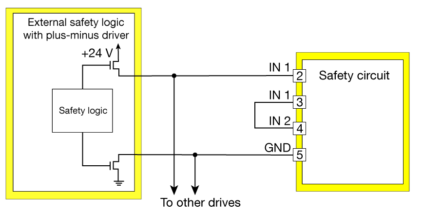
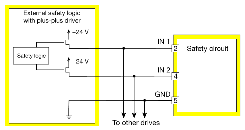
If safety PLCs are used it is important to distinguish between plus-plus and plus-minus logic
PLCs using plus-plus logic must be connected to both inputs for redundancy
PLCs using plus-minus logic are only connected to the input 1 which must be bridged to input 2. The redundant channel in this case is the pulsed safety ground signal.
Important
Please note that Safety GND is an isolated signal from drive GND.
Allows safety functions up to SIL 3, PL e, cat.3.
Note
Safety GND functions as a secondary line when a PLC with plus-minus output is used.
Attention
In case of multiple drive connection, ensure that the output driver has sufficient current driving capability.
Allows safety functions up to SIL 3, PL e, cat.3.
For example: Safety PLC output or safety sensors (e.g. Safety light curtain, safety scanner etc.)
Attention
In case of multiple drive connection, ensure that the output driver has sufficient current driving capability.
Attention
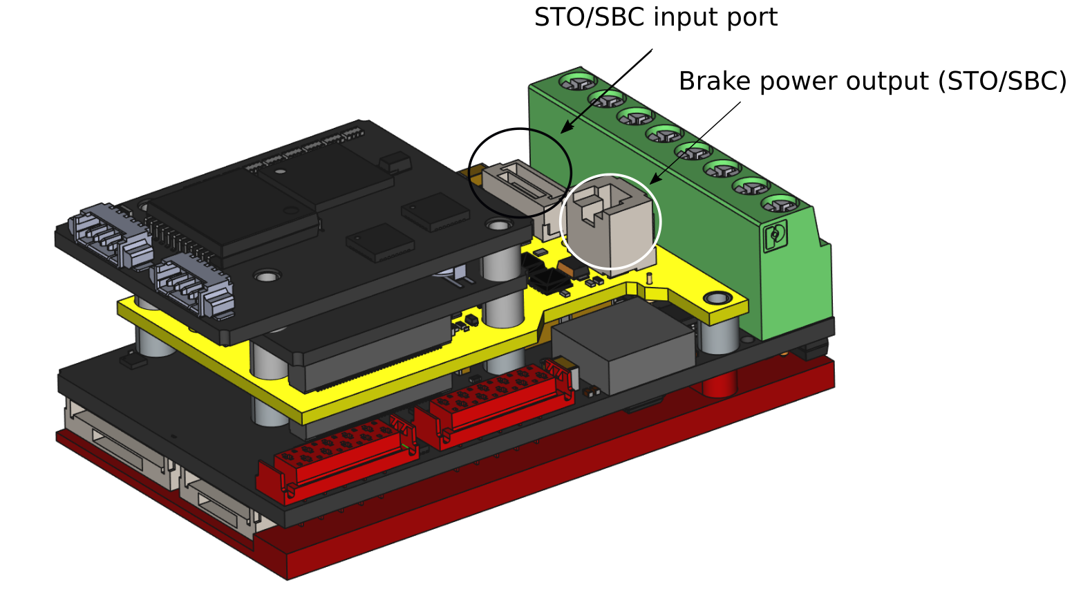
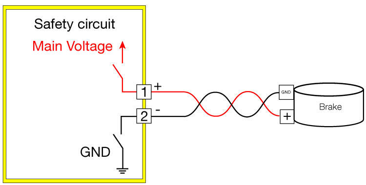
Phase D can’t be used for connecting a brake when Node Safety is used:
use the safety brake connector of the safety circuit (SBC out) instead of phase D of the drive circuit.
ensure to connect the brake GND signal to the Brake- signal of the safety circuit (SBC out) instead of the general GND.
Pin # |
Designation |
Function |
|---|---|---|
1 |
+ |
Brake + |
2 |
- |
Brake - |
Note
The safe brake is PWM based and can be configured with the regular brake object.
Connector description |
Manufacturer |
Mating part number |
Crimping Contact |
Cable |
|---|---|---|---|---|
Safe brake port |
JST |
ZER-02V-S |
SZE-002T-P0.3 |
0.08-0.21 mm² / 28-24 AWG |
Safe digital I/O port |
JST |
GHR-06V-S |
SSHL-002T-P0.2 |
0.05-0.13mm² / AWG 30-26 |
Please observe the maximum allowed cable lengths:
Connection |
Maximum wire length |
|---|---|
STO-SBC |
30 m |