- Hardware Manuals
- Commissioning and Tuning Guide
- Software Reference
- Resources
In this mode, the trajectory generator is located in the control device, not in the servo drive. In a cyclic synchronous manner, it provides a target torque to the drive device, which performs torque control. Optionally, an additive torque value can be provided by the control system in order to allow two instances to set up the torque.
The cyclic synchronous torque mode covers the following sub-functions:
demand value input;
torque capture;
torque control function with appropriate input and output signals;
limitation of torque demand.
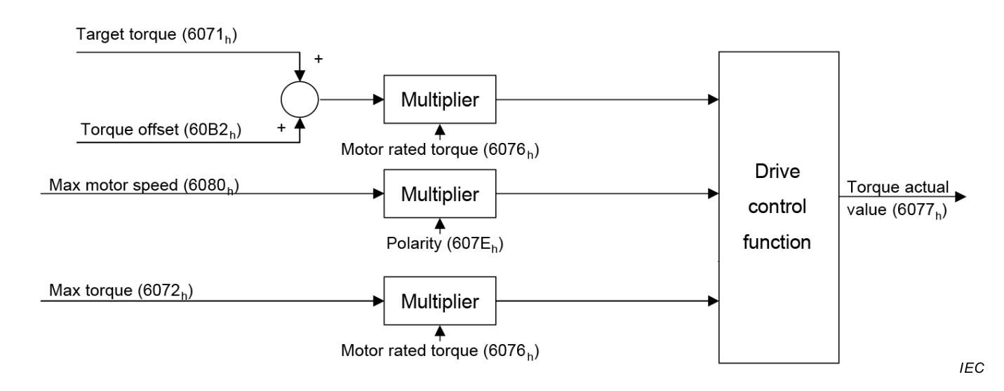
The figure above shows the inputs and outputs of the torque control function. The input (from the control function point of view) are the target torque and optionally a torque offset which is added to the target torque to allow two instances to set up the torque.
The torque can be limited in object 0x6072 Max torque.
The torque actual value is used as mandatory output to the control device.
This mode uses some bits of the statusword for mode specific purposes which are indicated in yellow. The figure shows the structure of the statusword. For the general structure and usage, please refer to our Application note on Status- and Controlword.
The mode specific bits of the statusword can be used to monitor the performance of the operation. For further information please refer to the section on Control Supervision.
| 15-13 | 12 | 11 | 10 | 9-8 | 7-0 | |||||
|---|---|---|---|---|---|---|---|---|---|---|
| N/A | Target Torque ignored | Internal limit active | Target reached | N/A | basic | |||||
Internal limit active:
Target reached: The bit is set if the actual torque stays in the window of target torque ± torque window value for a duration of torque window time.
Target torque ignored: This bit is set if Target torque 0x6071 is equal to Torque demand 0x6074.
It means that the user command is passed directly through as an input of the torque controller.
However, if Target torque is limited by Max torque, the limited value will be used as an input of the torque controller and the bit will be cleared.
Note
0 = Target torque ignored1 = Target torque shall be used as input
Values Kp, Ki and Kd for Torque Controller
Use this object to directly select a Target torque
This object provides the offset for the torque value.
