- Hardware Manuals
- Commissioning and Tuning Guide
- Software Reference
- Resources
Attention
For SIL 3, PL e, cat.3 it is required to send test pulses from the PLC to the output or to ensure fault exclusion for wiring “Short circuit between any two conductors” according to ISO 13849-2:2012 between signals STO-SBC 1 and STO SBC 2
permanently connected (fixed) and protected against external damage, e.g. by cable ducting, armouring, OR
separate multicore cables, OR
within an electrical enclosure, OR
individually shielded with earth connection.
Please observe the maximum allowed cable lengths:
Connection |
Maximum wire length |
|---|---|
STO-SBC |
30 m |
Important
Please note that Safety GND is an isolated signal from drive GND.
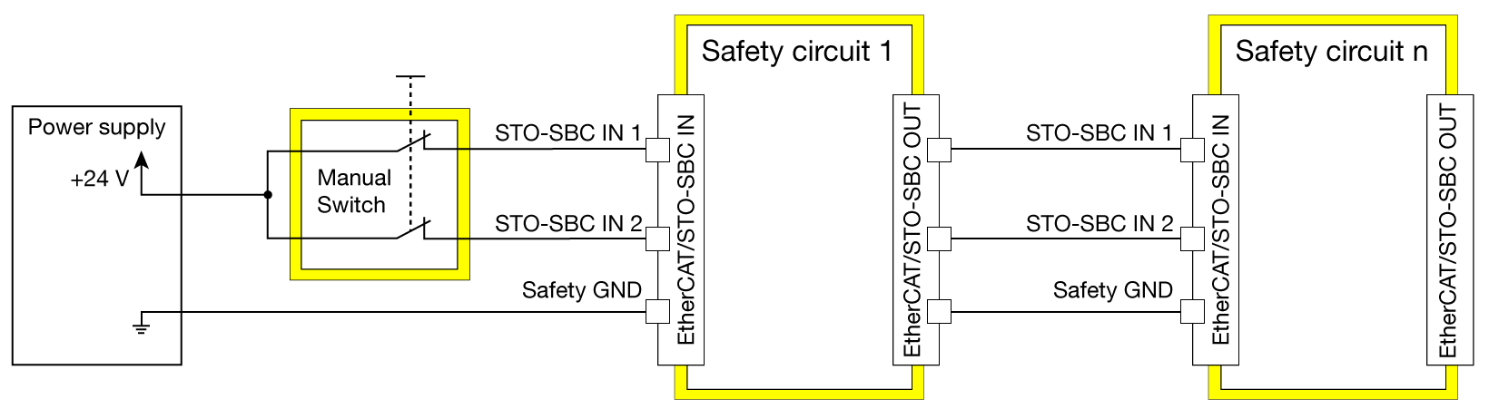
Allows safety functions up to SIL 3, PL e, cat.3.
Note
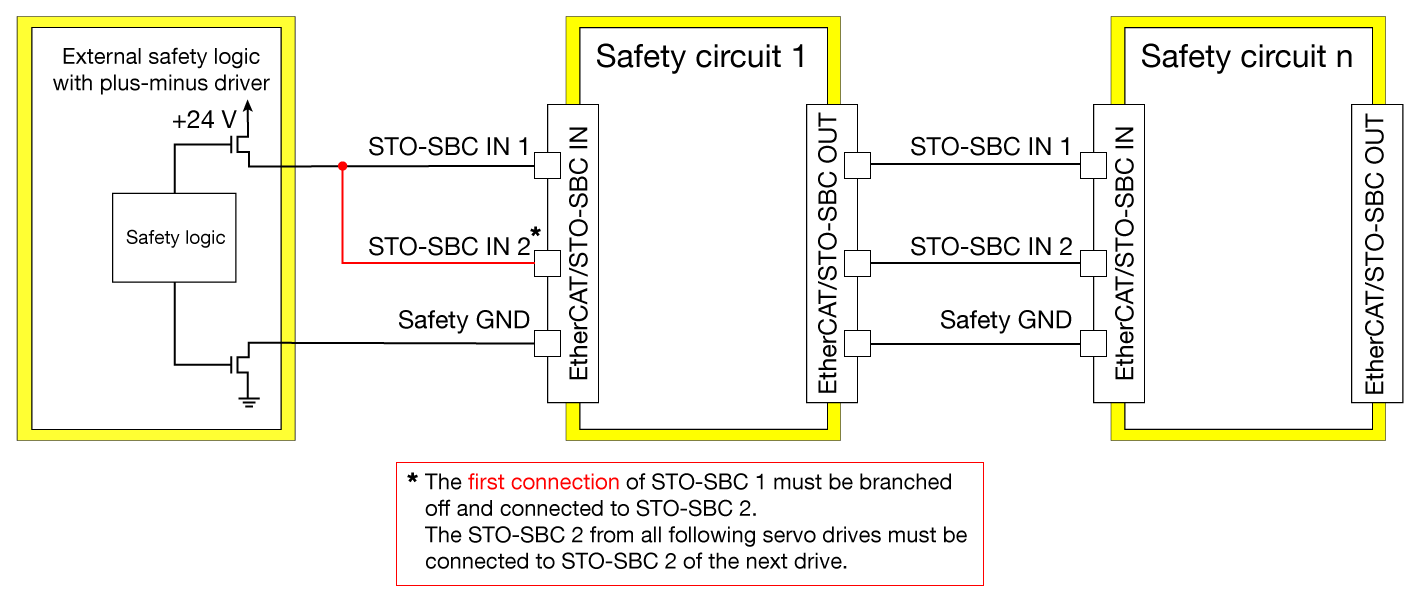
Safety GND functions as a secondary line when a PLC with Plus-Minus output is used.
Attention
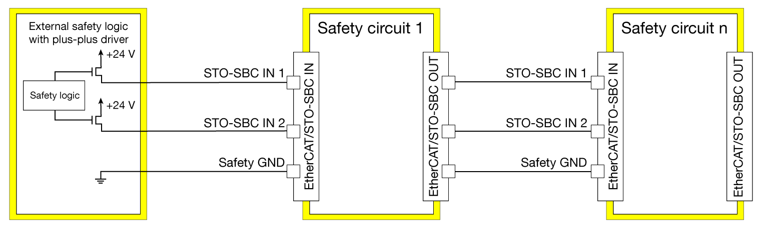
In case of multiple drive connection, ensure that the output driver has sufficient current driving capability.
Allows safety functions up to SIL 3, PL e, cat.3.
Attention
In case of multiple drive connection, ensure that the output driver has sufficient current driving capability.
Attention
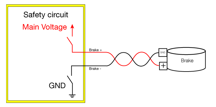
When using a safe brake ensure to connect the safe brake GND to Brake- instead of a general GND
Now you are ready to use the feature: