- Hardware Manuals
- Commissioning and Tuning Guide
- Software Reference
- Resources
When mounted properly, the encoder allows for high accuracy which guarantees the precise positioning of the actuator and also reduces encoder-based distortions in the control loop and leads to vibration-free motion.
A precise encoder allows achieving:
faster reaction time,
sharper position and velocity loops tuning,
better tracking of the dynamic trajectories.
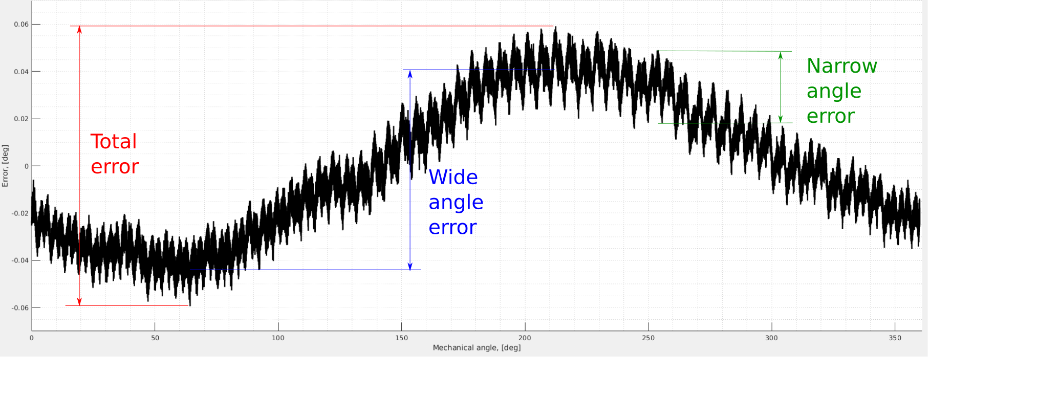
The total angle measurement error (non-linearity) of the encoder system is composed of 2 parts:
Wide angle errors (installation-dependent non-linearity): Non-linearity caused by imperfect mechanical installation.
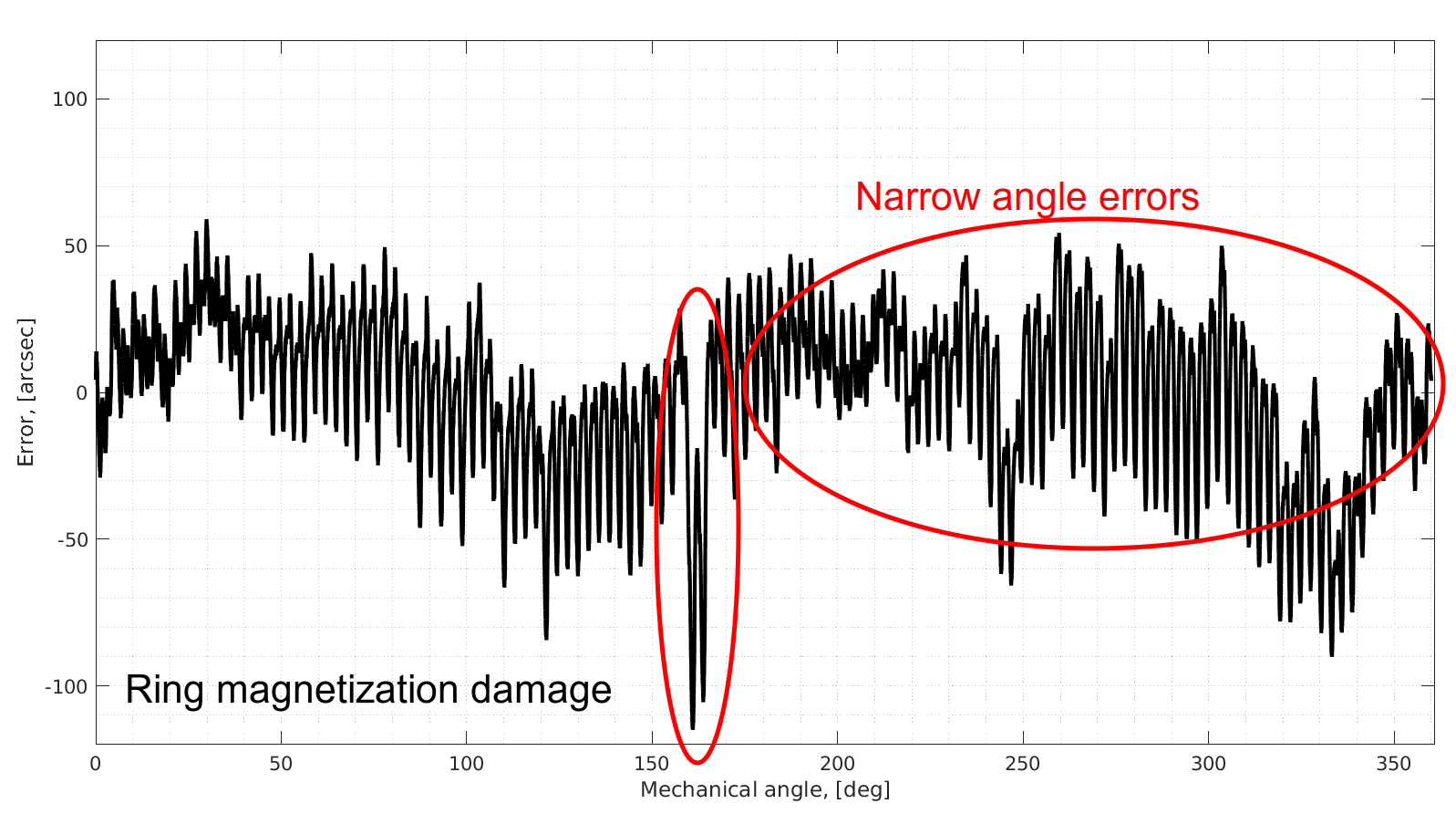
Narrow angle errors (encoder system-specific non-linearity) - encoder system limits and magnetic ring magnetization imperfections.
The following figure shows a typical non-linearity of the encoder:
This non-linearity is caused by the encoder system limitations.
There are 2 main sources:
analogue signals errors and
magnetic target magnetization errors.
It’s not possible to clearly distinguish the contribution of each error type but the total system-specific non-linearity is specified in the technical specifications.
This type of error initially appears in the analogue output of the magnetic field sensor on the chip or so-called sin/cos signals. These distortions come from:
Offsets in static positioning of the chip in respect to the ring
Imperfect air gap
Chip to chip circuitry deviations
These errors are mostly removed after the encoder calibration procedure. Some of the error is left and can’t be fully compensated. The amount of leftover error depends on particular installation conditions and severely increases with deviation from optimal installation position. Typical leftover narrow-angle error lies in the range given in the technical specifications provided that the installation requirements are met.
Please check the section Calibration procedure for calibrating the narrow angle.
Attention
The analogue calibration should be repeated if the mechanical setup was changed.
One of the main limitations of any encoder is the accuracy of the actuator or position encoding device. It can be an optical disk, magnetic ring or a capacitive system. Very accurate magnetic rings are expensive and further accuracy improvements result in exponential production complexity and hence price growth. Thus, there will always be some magnetization inaccuracies. However, their amplitude is smaller than the Analogue signal errors.
This type of error is the most dominant and caused by imperfect mechanical assembly. If the magnetic ring rotates with some axial or radial runout (so-called eccentricity), then this will be reflected in the overall accuracy. The eccentricity is typically caused by a mismatch between a geometric center of the ring and the actual rotation center.
The effect of the eccentricity-caused error can be computed based on geometrical properties of the encoder system after installation.
Err ecc = 3600 
where:
Err ecc: amplitude of the eccentricity-caused error [″]
e: eccentricity of the rotational axis (or radial runout of the ring) [mm]
R: sensing radius of the corresponding Circulo encoder [mm]
This table below shows maximum installation-caused error given that the maximum eccentricity is 0.1 mm.
Circulo encoder ring |
Position 1 (inner) |
Position 2 (outer) |
|---|---|---|
Sensor location (radius) [mm] |
14.975 |
22.875 |
Wide angle error at eccentricity e = 0.1 mm, [arcsec] |
±1377 |
±902 |
Wide angle error at eccentricity e = 0.1 mm, [deg] |
±0.38 |
±0.25 |
Circulo encoder ring |
Position 1 (inner) |
Position 2 (outer) |
|---|---|---|
Sensor location (radius) [mm] |
24.975 |
32.475 |
Wide angle error at eccentricity e = 0.1 mm, [arcsec] |
±826 |
±635 |
Wide angle error at eccentricity e = 0.1 mm, [deg] |
±0.23 |
±0.18 |
This table shows that this type of non-linearity is one order of magnitude bigger than the encoder-specific errors. Thus, it is extremely important to produce encoder-relevant mechanical parts with the highest precision possible to achieve good encoder accuracy.
To inspect the effect of the wide angle error, rotate the encoder ring at a constant velocity that is a multitude of 60 RPM (60 RPM = 1 Hz).
Since the error has a peak once or more times per mechanical revolution, the frequency of the distortion will be a multiple of the mechanical rotation frequency (Rotations Per Second, RPS).
The multitude of this frequency indicates the origin of the error:
1 x RPS - Eccentricity of the magnetic ring axis
2 x RPS - Ovality of the magnetic ring
3-8 x RPS - mounting of the magnetic ring (for example amount of the screws used for fixing the ring)
