- Hardware Manuals
- Commissioning and Tuning Guide
- Software Reference
- Resources
The Anti-windup control algorithm is implemented with the following approach:
with:
: control deviation
: Output of the integral part
: Sample time
: Integral gain
: Integrator limit
Explanation: If the integral part of the controller goes higher than the value of the controller’s output limit, the value that was previously added to integral is automatically subtracted.
This method is known as “clamping”. It requires no tuning.
Detail view on the integrator branch with anti-windup:
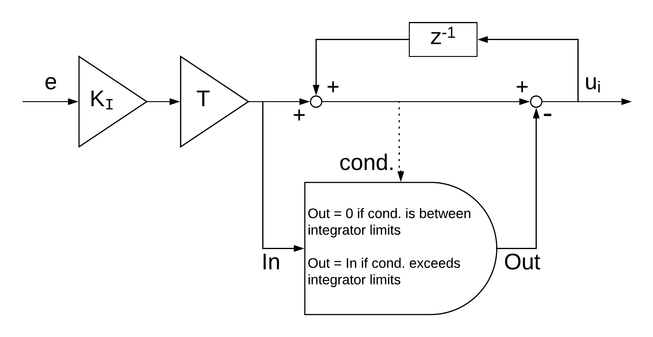
The described implementation of the integration algorithm is used in all motion controllers (both integrators of the cascaded position controller, integrator of the PID position controller, integrator of the PID velocity controller). The variable Integrator limit is defined by the subitems 2012:4, 2012:8 and 2011:4 respectively.
Values Kp, Ki, Kd and Integrator Limit for Velocity Controller
Values Kp, Ki, Kd and Integrator Limit for Cascaded Position Controller (Both loops: Position and Velocity)


