- Hardware Manuals
- Commissioning and Tuning Guide
- Software Reference
- Resources
The analog input value is converted into digital ticks from 0 (representing U min of the selected input, e.g. -5V) to 65535 (representing U max of the selected input, e.g. +5V) which must be computed externally for further use.
This feature allows a nonlinear conversion of one of the available analog inputs using a polynomial function up to 5th order and to read the value directly.
It’s also possible to describe a voltage divider connected to the analog input for sensors that output a resistance as measurement value.
Use case: Temperature sensor
Applications include converting the output of a temperature sensor directly into degrees Celsius, Fahrenheit or any other unit desired by the user.
For details about using temperature sensors please check our System integration guide.
Use case: Torque sensor
Applications include converting the output of a torque sensor directly into mNm, Nm or any other unit desired by the user.
The hardware must support at least one analog input
For SOMANET Node, please follow this wiring scheme when attaching an external voltage divider.
Drives of the SOMANET Circulo family has a voltage divider internally.
The object used for this feature is 0x2038 Analog Input Scaling. The converted value will be reflected in Subitem 0x2038:1.
The polynomial used for the conversion can be described with the parameters “Constant a0” (0x2038:4) to “Constant a5” (0x2038:9), which are the coefficients for the polynomial function.
The analog input to be used can be defined using the parameter “Analog input” in subitem 0x2038:2. This parameter has 5 possible options, which are the 4 standard analog inputs (values: 1-4) and another analog input called internal (value: 0). The internal analog input is only available in SOMANET Circulo.
Analog input selection k (0x2038:2): Select the scaled measurement source. Values:
1 = Analog Input 1
2 = Analog Input 2
3 = Analog Input 3
4 = Analog Input 4
0 = Internal ADC (if supported, for example SOMANET Circulo 7/9)
The unscaled raw analog input values are filtered through a first order low pass filter before they are scaled. The cut-off frequency of this low-pass filter can be configured in subitem 0x2038:10.
Note
The external scaled measurement feature is using the filtered analog input value. Therefore all the analog inputs mentioned in this section are referring to the filtered analog input.
A 5th order polynomial function with or without voltage-divider is supported.
This feature is also designed to have a different behavior depending on the value of the parameter “Resistance” (0x2038:3). If this value is set to 0, the polynomial will be directly applied to the value of the ADC count, which has a range of 0-65535 (0 to V cc).
If a voltage divider is connected to the analog input, as shown in the figure below, the value of the “Resistance” parameter (0x2038:3) defines the value of the pull-up resistor R p of this voltage divider.
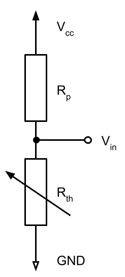
V cc represents the value of voltage at which the ADC is connected to, causing the ADC to count an output of 65535.
R p represents the pull-up resistor.
R th is a resistive sensor, e.g. a thermistor or strain gauge.
V in is the voltage that is connected to the selected analog input.
The cut-off frequency of the low-pass filter (0x2038:10) for the analog input can also be tweaked to further fine-tune the unscaled analog input before feeding it to the scaling algorithm.
Upper and lower level thresholds can be configured in subitems 0x2038:11 and 0x2038:12. When these thresholds are breached, the error ExAnSnsr is triggered in the Error report object.
Note
When the value approaches 95% of the defined thresholds, a warning is triggered.
If R p := 0 (no voltage divider)
If R p > 0 (user specified pull-up resistor for voltage divider)
with
The coefficients and the pull-up resistor values are specified in object 0x2038, subitems 2-9
0x2038:3 (Resistance R): Select the pull-up resistor connected to the selected analog input. Value is given in Ohm.
0x2038:4 (Constant a0): Constant a0 of the polynomial (Offset).
0x2038:5 (Constant a1): Constant a1 of the polynomial (1st order coefficient)
0x2038:6 (Constant a2): Constant a2 of the polynomial (2nd order coefficient)
0x2038:7 (Constant a3): Constant a3 of the polynomial (3rd order coefficient)
0x2038:8 (Constant a4): Constant a4 of the polynomial (4th order coefficient)
0x2038:9 (Constant a5): Constant a5 of the polynomial (5th order coefficient)
Transforms an analog input to an output by a 5th order polynomial


