- Hardware Manuals
- Commissioning and Tuning Guide
- Software Reference
- Resources
Axes without an absolute encoder can use the homing function to restore the position to a previously defined location.
SOMANET supports the following methods as defined in CiA 402 profile specification (IEC61800-7-201:2015):
1 - Homing on a negative limit switch and index pulse
2 - Homing on a positive limit switch and index pulse
3 - Homing on a positive home switch inactive and index pulse
4 - Homing on a positive home switch active and index pulse
5 - Homing on a negative home switch inactive and index pulse
6 - Homing on a negative home switch active and index pulse
7 - Homing on a home switch (inactive) and index pulse with positive initial direction. Reverse if positive limit switch is hit.
8 - Homing on a home switch (active) and index pulse with positive initial direction. Reverse if positive limit switch is hit.
9 - Homing on an opposite home switch (active) and index pulse with positive initial direction. Reverse if positive limit switch is hit.
10 - Homing on an opposite home switch (inactive) and index pulse with positive initial direction. Reverse if positive limit switch is hit.
11 - Homing on a home switch (inactive) and index pulse with negative initial direction. Reverse if negative limit switch is hit.
12 - Homing on a home switch (active) and index pulse with negative initial direction. Reverse if negative limit switch is hit.
13 - Homing on an opposite home switch (active) and index pulse with negative initial direction. Reverse if negative limit switch is hit.
14 - Homing on an opposite home switch (inactive) and index pulse with negative initial direction. Reverse if negative limit switch is hit.
33 - Homing on an index pulse with negative initial direction.
34 - Homing on an index pulse with positive initial direction.
35/37 (identical) - Homing on the current position.
In all switch based homing methods the axis moves to search the switch (Home Switch or Limit Switch).
The following images represent the direction of movement and the starting position of each homing method.
The respective method is indicated by the encircled number.
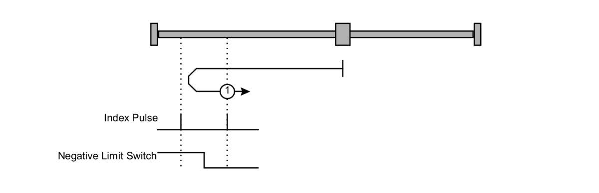
The initial direction of movement shall be leftward if the negative limit switch is inactive.
The home position is the first index to the right when the negative limit switch changes state.
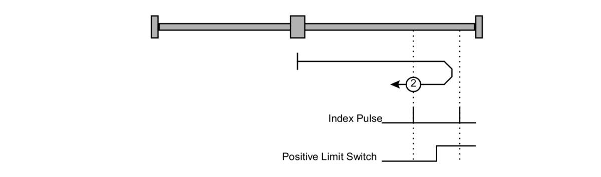
The initial direction of movement shall be rightward if the positive limit switch is inactive.
The home position is the first index to the left when the positive limit switch changes state.
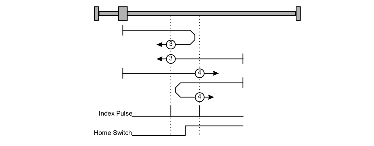
The initial direction of movement is dependent on the state of the home switch: leftward if positive home switch active and rightward if it’s inactive.
Method 3: the home position is the first index to the left when the positive home switch changes state (home switch inactive).
Method 4: the home position is the first index to the right when the positive home switch changes state (home switch active).
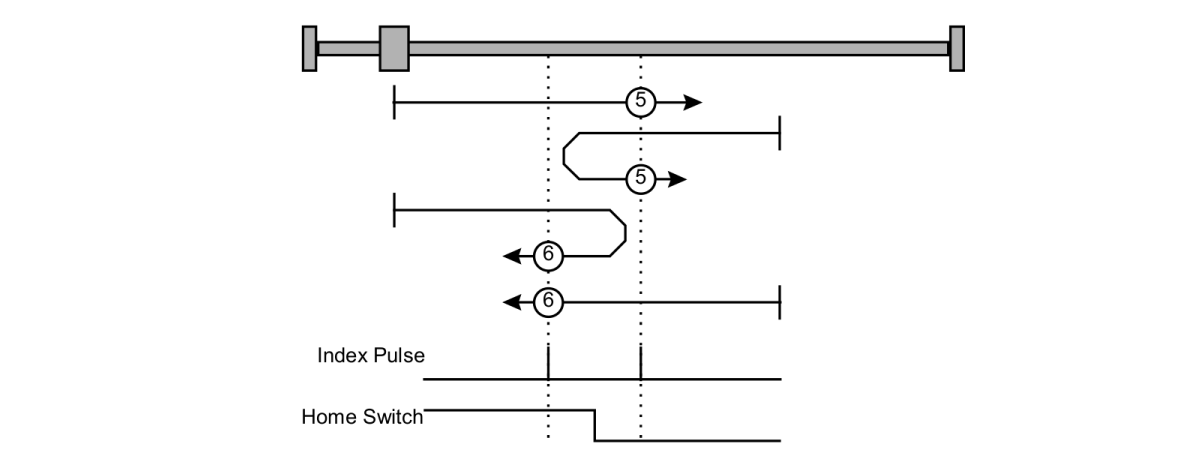
The initial direction of movement is dependent on the state of the home switch: leftward if negative home switch inactive and rightward if it’s active.
Method 5: the home position is the first index to the right when the negative home switch changes state (home switch inactive).
Method 6: the home position is the first index to the left when the negative home switch changes state (home switch active).
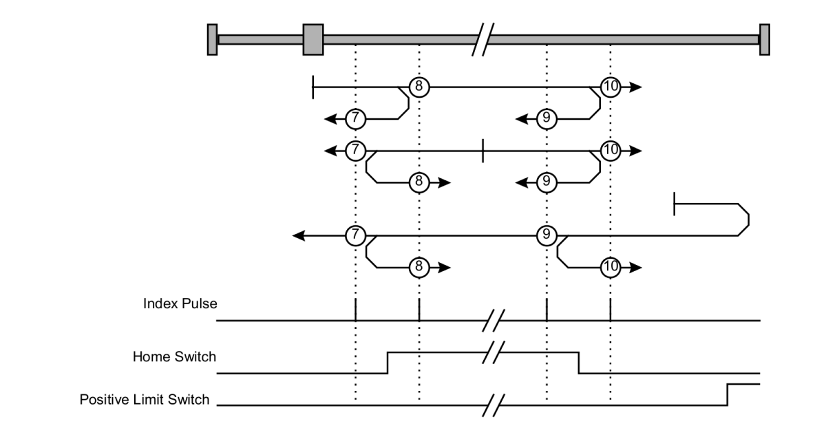
The initial direction of the movement is rightward except if home switch is initially active.
If the home switch is initially active then the direction of movement depends on the homing method.
The direction will be reversed when encountering the positive limit switch.
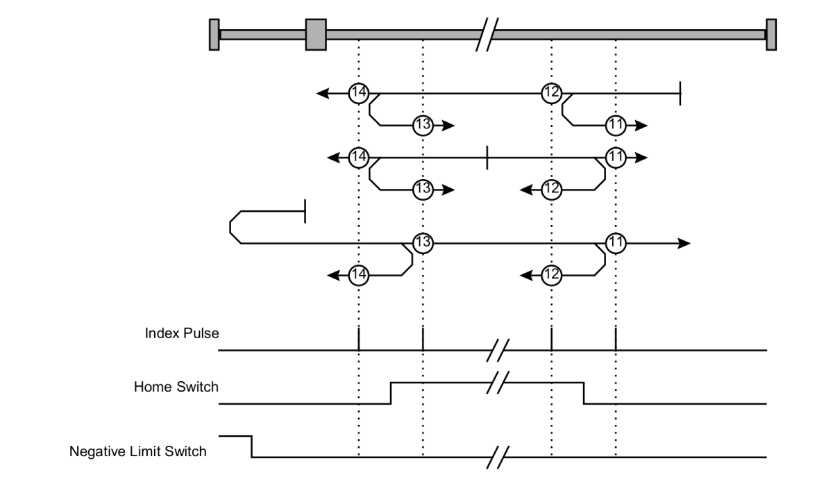
The initial direction of the movement is leftward except if home switch is initially active.
The direction will be reversed when encountering the negative limit switch.
If the home switch is initially active then the direction of movement depends on the homing method.
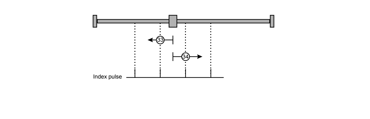
Methods 33 and 34 can be used to center on the sensor’s reference position (in positive or negative direction).
The shaft will rotate less than one rotation.
Methods 35 and 37 are used to define the current position as home position.
Note
Homing method 35/37 can be performed in any operational state. All other homing methods require the drive to be in “operation enabled” state.
Use case: Homing on current position while operation is not enabled
If the axis is moved to a desired homing position by external force (for example manually), Homing Mode 35/37 can be used to determine the current position as home.
Use case: Relative position command
The current position can be taken as the reference point.
Use case: Homing on current position
When the motor is moved to the desired position in CSP the position can be taken as homing position.
All homing methods except for methods 35/37 require the drive to be in the “operation enabled” state. After the home position is found, the position controller stays active, holding the motor at that position (except for method 35/37).
You can select the desired homing method in object 0x6098: Homing Method.
Mode |
Description |
|---|---|
0 |
No homing method assigned (Default) |
1 |
Homing on negative home switch and index pulse |
2 |
Homing on positive home switch and index pulse |
3,4 |
Homing on positive home switch and index pulse |
5,6 |
Homing on negative home switch and index pulse |
7 to 14 |
Homing on the home switch with an index pulse |
17, 18 |
Similar to method 1 & 2 but without index pulse. Homing is done at switch transition |
19 to 22 |
Similar to methods 3 to 6, but without index pulse. Homing is done at switch transition |
23 to 30 |
Similar to method 7 to 14 but without index pulse. Homing is done at switch transition |
33 |
Homing on negative index pulse |
34 |
Homing on positive index pulse |
35 |
Homing on current position. (deprecated, please use method 37) |
37 |
Homing on current position. (identical with method 35) |
Two homing speeds must be selected in object 0x6099: Homing Speed: in a typical cycle, the faster speed is used to find the home switch and the slower speed is used to find the index pulse.
Note
Homing speeds are not required in method 35/37.
In object 0x609A: Homing Acceleration a value for acceleration during homing must be defined.
Note
An acceleration is not needed in method 35/37.
Object 0x2210 (GPIO Pin configuration) is used to configure the digital inputs for homing and limit switches. Switches can be configured in both active high and active low configuration. But only one GPIO can be assigned to one switch whether active high or active low. For example If Pin 3 is configured as Active High Limit Switch, then configuring any other pin as Limit Switch Active High or Active Low will raise the error IvldGpio (Invalid GPIO error) in the error report object.
Further details about configuring digital I/Os can be found in Digital GPIO
Object 0x60FD (Digital inputs) reports the state of the digital inputs which can be configured for limit switches, interlock, etc.
The following diagram shows the steps that are necessary to perform the homing function.
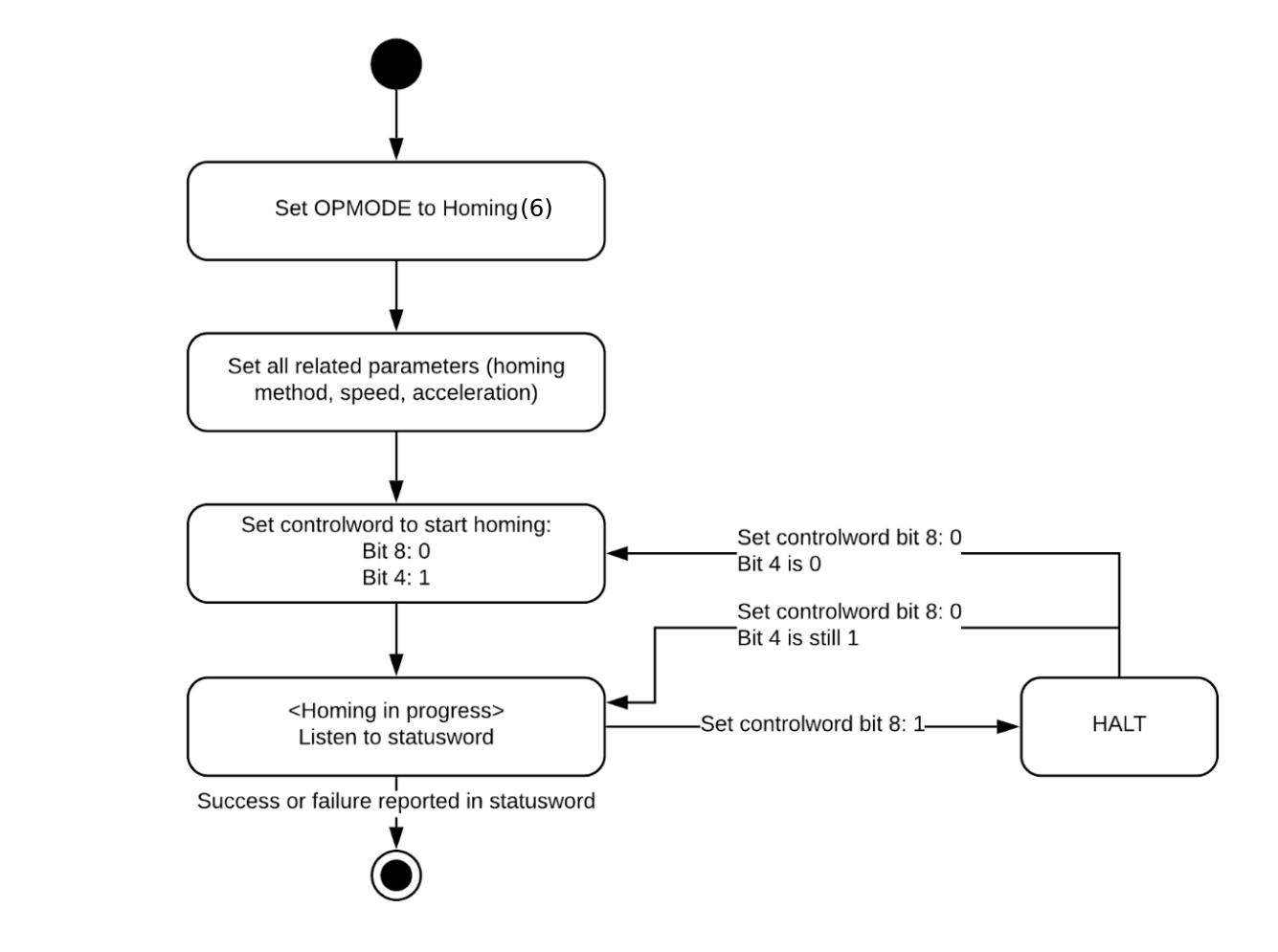
After the home position is found, the position controller stays active, holding the motor at that position (except for method 35/37).
The halt bit (bit 8 of the Controlword 0x6040 can be used to stop the drive without disabling the controller:
Set the halt bit to 1 to stop the motion
When the halt bit is reset to 0, the motion continues
Bits 10, 12, 13 of the Statusword 0x6041 are used to indicate the current state of the homing process:
Bit 13: Homing error
Bit 12: Homing attained
Bit 10: Target reached
Bit 13 |
Bit 12 |
Bit 10 |
Status |
|---|---|---|---|
0 |
0 |
0 |
Homing is performed |
0 |
0 |
1 |
Homing is interrupted or not started |
0 |
1 |
0 |
Homing confirmed, but target not yet reached |
0 |
1 |
1 |
Homing completed |
1 |
0 |
0 |
Error detected, motor still turning |
1 |
0 |
1 |
Error during homing, motor at standstill |
Homing modes are meant to be used with homing switches whereas limit switches are considered as physical end points.
When a limit switch is activated in a homing mode other than method 1-14 (which rely on limit switches), this is considered a fault and the drive transitions to “Drive disabled” state.
Homing mode uses some bits of the controlword for mode specific purposes which are indicated in yellow. The figure shows the structure of the controlword. For the general structure and usage, please refer to our Application note on Status- and Controlword.
| 15-9 | 8 | 7-5 | 4 | 3-0 | |||||||||||
|---|---|---|---|---|---|---|---|---|---|---|---|---|---|---|---|
| N/A | Halt | N/A | Homing operation start | basic | |||||||||||
Halt: If halt is triggered (Bit 8 of control word is set as 1) during homing, independant of the step the homing routine is in, Axis begins to ramp down to go to zero velocity. The axis stays at zero velocity as long as the halt remains active. When the halt bit is lifted, the homing routine is resumed from the same step it was in before halt.
Homing operation start: set the homing operation start bit to 1 to start the homing procedure.
The mode specific bits of the statusword can be used to monitor the performance of the operation. For further information please refer to the section on Control Supervision.
| 15-14 | 13 | 12 | 11 | 10 | 9-8 | 7-0 | |||||||||
|---|---|---|---|---|---|---|---|---|---|---|---|---|---|---|---|
| N/A | Homing error | Homing attained | Internal limit active | Target reached | N/A | basic | |||||||||
Specifies the homing method that shall be used.
Offset from user’s zero position to the home position.
Speed with which to move during homing.
Acceleration used during homing.
Set bit 8 to 0 and bit 4 to 1 to start homing.
Indicates the current state of the homing process.
Indicates the current state of the digital inputs
Configures the digital inputs for homing and limit switches
Note
Switches can be configured in both active high and active low configuration. But only one GPIO can be assigned to one switch whether active high or active low. For example If Pin 3 is configured as Active High Limit Switch, then configuring any other pin as Limit Switch Active High or Active Low will raise IvldGpio (Invalid GPIO error).
